
Arduino Nano and LoRa SX1278 Battery-Powered Air Quality Monitor
View and Edit Project In Cirkit Designer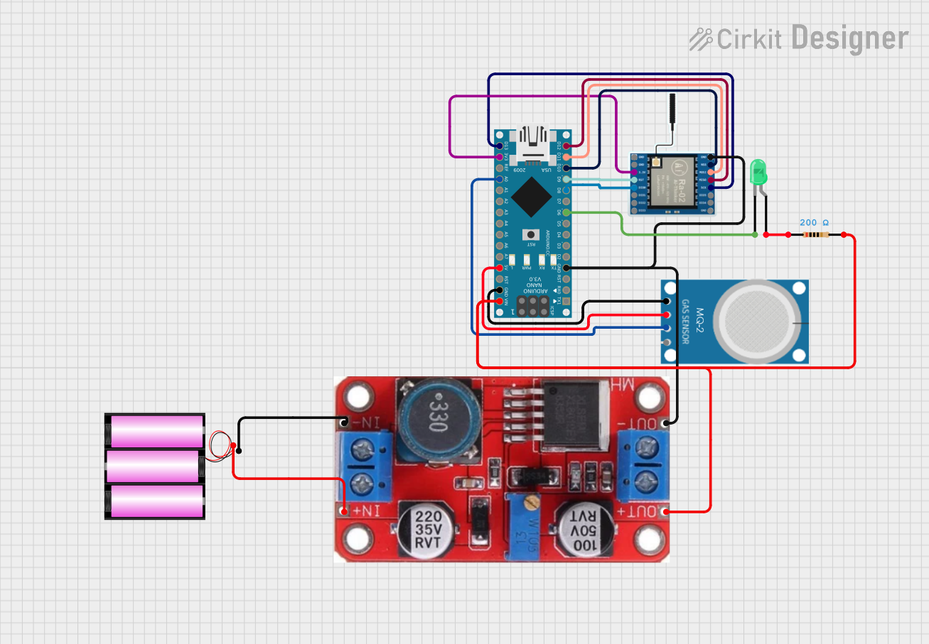
Circuit Documentation
Summary
This document provides a detailed overview of a circuit that includes an Arduino Nano, a LoRa Ra-02 SX1278 module, an XL6015 buck converter, a 12V battery, a green LED, an MQ-2 gas sensor, and a resistor. The circuit is designed to interface the Arduino Nano with the LoRa module for wireless communication, power the system using a 12V battery, and include a gas sensor and an LED indicator.
Component List
Arduino Nano
- Description: A small, complete, and breadboard-friendly board based on the ATmega328P.
- Pins: D1/TX, D0/RX, RESET, GND, D2, D3, D4, D5, D6, D7, D8, D9, D10, D11/MOSI, D12/MISO, VIN, 5V, A7, A6, A5, A4, A3, A2, A1, A0, AREF, 3V3, D13/SCK
LoRa Ra-02 SX1278
- Description: A wireless communication module based on the SX1278 chip.
- Pins: GND, NSS, MOSI, MISO, SCK, D105, DI04, 3.3V, RST, DI00, DI01, D102, DI03
XL6015 Buck Converter
- Description: A DC-DC buck converter for stepping down voltage.
- Pins: INPUT -, INPUT +, OUTPUT +, OUTPUT -
Battery 12V
- Description: A 12V battery for powering the circuit.
- Pins: +, -
LED: Two Pin (green)
- Description: A green LED for visual indication.
- Pins: cathode, anode
MQ-2 Gas Sensor
- Description: A gas sensor for detecting various gases.
- Pins: GND, VCC, ANALOG, Digital
Resistor
- Description: A resistor with a resistance of 200 Ohms.
- Pins: pin1, pin2
Wiring Details
Arduino Nano
GND is connected to:
- GND of LoRa Ra-02 SX1278
- OUTPUT - of XL6015 Buck Converter
- GND of MQ-2 Gas Sensor
D6 is connected to the cathode of the green LED.
D8 is connected to DI00 of LoRa Ra-02 SX1278.
D9 is connected to RST of LoRa Ra-02 SX1278.
D10 is connected to NSS of LoRa Ra-02 SX1278.
D11/MOSI is connected to MOSI of LoRa Ra-02 SX1278.
D12/MISO is connected to MISO of LoRa Ra-02 SX1278.
VIN is connected to OUTPUT + of XL6015 Buck Converter and pin2 of the resistor.
5V is connected to VCC of MQ-2 Gas Sensor.
A0 is connected to ANALOG of MQ-2 Gas Sensor.
3V3 is connected to 3.3V of LoRa Ra-02 SX1278.
D13/SCK is connected to SCK of LoRa Ra-02 SX1278.
LoRa Ra-02 SX1278
GND is connected to GND of Arduino Nano and OUTPUT - of XL6015 Buck Converter.
DI00 is connected to D8 of Arduino Nano.
RST is connected to D9 of Arduino Nano.
NSS is connected to D10 of Arduino Nano.
MOSI is connected to D11/MOSI of Arduino Nano.
MISO is connected to D12/MISO of Arduino Nano.
3.3V is connected to 3V3 of Arduino Nano.
SCK is connected to D13/SCK of Arduino Nano.
XL6015 Buck Converter
OUTPUT - is connected to GND of Arduino Nano and GND of LoRa Ra-02 SX1278.
OUTPUT + is connected to VIN of Arduino Nano and pin2 of the resistor.
INPUT - is connected to - of the 12V battery.
INPUT + is connected to + of the 12V battery.
Battery 12V
- is connected to INPUT - of XL6015 Buck Converter.
+ is connected to INPUT + of XL6015 Buck Converter.
LED: Two Pin (green)
cathode is connected to D6 of Arduino Nano.
anode is connected to pin1 of the resistor.
MQ-2 Gas Sensor
GND is connected to GND of Arduino Nano.
VCC is connected to 5V of Arduino Nano.
ANALOG is connected to A0 of Arduino Nano.
Resistor
pin1 is connected to the anode of the green LED.
pin2 is connected to OUTPUT + of XL6015 Buck Converter and VIN of Arduino Nano.
Documented Code
Arduino Nano Code (sketch.ino)
void setup() {
  // put your setup code here, to run once:

}

void loop() {
  // put your main code here, to run repeatedly:

}
Documentation (documentation.txt)
This document provides a comprehensive overview of the circuit, including a summary, component list, wiring details, and documented code.