Cirkit Designer
Your all-in-one circuit design IDE
Home /
Project Documentation
555 Timer IC LED Flasher Circuit with 9V Battery
Circuit Documentation
Summary
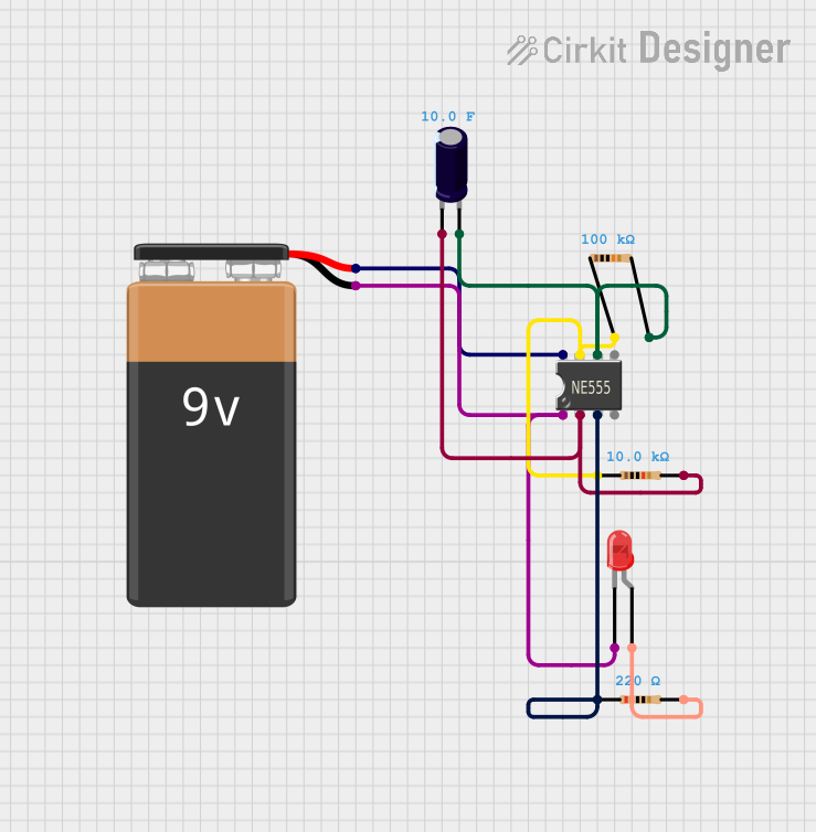
This document provides a detailed description of a circuit that utilizes a 555 Timer IC to drive an LED. The circuit is powered by a 9V battery and includes resistors and a capacitor to configure the 555 Timer IC in astable mode, which causes the LED to blink at a specific frequency.
Component List
555 Timer IC
- Description: A versatile timer IC used for generating precise time delays or oscillation.
- Pins: VCC+, Dis, Th, CV, Rst, Out, Trig, GND
9V Battery
- Description: A standard 9V battery used to power the circuit.
- Pins: +, -
Resistor (100k Ohms)
- Description: A resistor with a resistance of 100k Ohms.
- Pins: pin1, pin2
Electrolytic Capacitor (10 Farads)
- Description: A capacitor with a capacitance of 10 Farads.
- Pins: +, -
Resistor (10k Ohms)
- Description: A resistor with a resistance of 10k Ohms.
- Pins: pin1, pin2
LED: Two Pin (red)
- Description: A red LED with two pins.
- Pins: cathode, anode
Resistor (220 Ohms)
- Description: A resistor with a resistance of 220 Ohms.
- Pins: pin1, pin2
Wiring Details
555 Timer IC
- VCC+ is connected to the + pin of the 9V Battery.
- Dis is connected to pin1 of the 100k Ohms Resistor and pin1 of the 10k Ohms Resistor.
- Th is connected to the + pin of the 10 Farads Electrolytic Capacitor and pin2 of the 100k Ohms Resistor.
- Out is connected to pin1 of the 220 Ohms Resistor.
- Trig is connected to the - pin of the 10 Farads Electrolytic Capacitor and pin2 of the 10k Ohms Resistor.
- GND is connected to the - pin of the 9V Battery and the cathode of the red LED.
9V Battery
- + is connected to the VCC+ pin of the 555 Timer IC.
- - is connected to the GND pin of the 555 Timer IC and the cathode of the red LED.
Resistor (100k Ohms)
- pin1 is connected to the Dis pin of the 555 Timer IC and pin1 of the 10k Ohms Resistor.
- pin2 is connected to the Th pin of the 555 Timer IC and the + pin of the 10 Farads Electrolytic Capacitor.
Electrolytic Capacitor (10 Farads)
- + is connected to the Th pin of the 555 Timer IC and pin2 of the 100k Ohms Resistor.
- - is connected to the Trig pin of the 555 Timer IC and pin2 of the 10k Ohms Resistor.
Resistor (10k Ohms)
- pin1 is connected to the Dis pin of the 555 Timer IC and pin1 of the 100k Ohms Resistor.
- pin2 is connected to the - pin of the 10 Farads Electrolytic Capacitor and the Trig pin of the 555 Timer IC.
LED: Two Pin (red)
- cathode is connected to the GND pin of the 555 Timer IC and the - pin of the 9V Battery.
- anode is connected to pin2 of the 220 Ohms Resistor.
Resistor (220 Ohms)
- pin1 is connected to the Out pin of the 555 Timer IC.
- pin2 is connected to the anode of the red LED.
Code
There is no microcontroller code associated with this circuit.