Cirkit Designer
Your all-in-one circuit design IDE
Home /
Project Documentation
ESP32-Based Wi-Fi Controlled Laser Shooting Game with OLED Display
Circuit Documentation
Summary
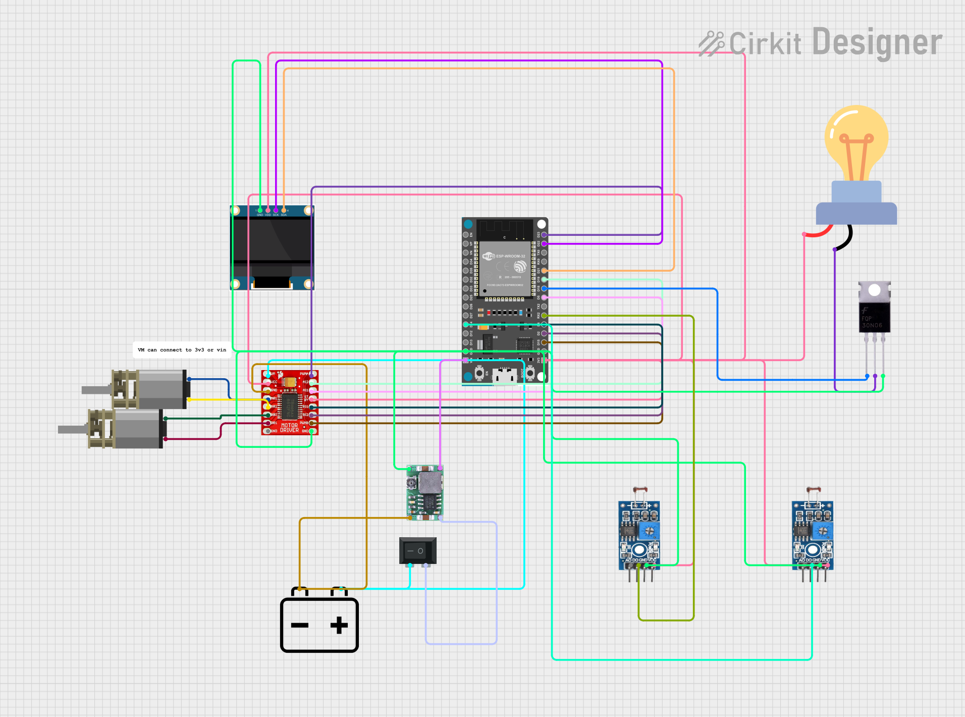
This circuit is designed to control a motorized system using an ESP32 microcontroller, a TB6612FNG motor driver, and various sensors and actuators. The system includes two photosensitive sensor modules for light intensity detection, a 0.96" OLED display for visual feedback, a DC Mini Metal Gear Motor for movement, and a laser controlled by a MOSFET. The circuit is powered by a 12V battery, regulated down to 3.3V using a Mini-360 DC-DC Step Down Buck Converter. The ESP32 microcontroller is programmed to handle motor control, sensor readings, and display updates.
Component List
Photosensitive Sensor Module Digital Light Intensity Detection
- Description: Detects light intensity and provides both analog and digital outputs.
- Pins: Analog Output, Digital Output, Ground, VCC
DC Mini Metal Gear Motor
- Description: A small DC motor with metal gears for precise control.
- Pins: IN1, IN2
TB6612FNG Motor Driver
- Description: Dual motor driver capable of driving two DC motors.
- Pins: GND, B01, B02, A02, A01, VCC, VM, PWMB, BI2, BI1, STBY, AI1, AI2, PWMA
0.96" OLED
- Description: Small OLED display for visual feedback.
- Pins: GND, VDD, SCK, SDA
ESP32 Devkit V1
- Description: Microcontroller with Wi-Fi and Bluetooth capabilities.
- Pins: 3V3, GND, D15, D2, D4, RX2, TX2, D5, D18, D19, D21, RX0, TX0, D22, D23, EN, VP, VN, D34, D35, D32, D33, D25, D26, D27, D14, D12, D13, VIN
Mosfet
- Description: Used to control the laser.
- Pins: Gate, Drain, Source
12V Battery
- Description: Power source for the circuit.
- Pins: -, +
Rocker Switch (SPST)
- Description: Simple on/off switch.
- Pins: 1, 2
Mini-360 DC-DC Step Down Buck Converter
- Description: Converts 12V to 3.3V for the ESP32 and other components.
- Pins: Input -, Input +, Output +, Output -
LED bulb AC / Bombillo AC
- Description: LED bulb for visual indication.
- Pins: +, -
Wiring Details
Photosensitive Sensor Module Digital Light Intensity Detection
- Ground: Connected to GND (common ground)
- VCC: Connected to 3V3 (common power supply)
- Digital Output:
- First module: Connected to ESP32 pin D14
- Second module: Connected to ESP32 pin RX2
DC Mini Metal Gear Motor
- IN1:
- First motor: Connected to TB6612FNG pin B01
- Second motor: Connected to TB6612FNG pin A02
- IN2:
- First motor: Connected to TB6612FNG pin B02
- Second motor: Connected to TB6612FNG pin A01
TB6612FNG Motor Driver
- GND: Connected to common ground
- VCC: Connected to 3V3 (common power supply)
- VM: Connected to 12V battery through Rocker Switch pin 2
- PWMB: Connected to ESP32 pin D15
- BI2: Connected to ESP32 pin D2
- BI1: Connected to ESP32 pin D4
- STBY: Connected to 3V3 (common power supply)
- AI1: Connected to ESP32 pin D5
- AI2: Connected to ESP32 pin D19
- PWMA: Connected to ESP32 pin D23
0.96" OLED
- GND: Connected to common ground
- VDD: Connected to 3V3 (common power supply)
- SCK: Connected to ESP32 pin D22
- SDA: Connected to ESP32 pin D21
ESP32 Devkit V1
- 3V3: Connected to 3V3 (common power supply)
- GND: Connected to common ground
- VIN: Connected to Mini-360 DC-DC Step Down Buck Converter Output +
- D18: Connected to Mosfet Gate
- D14: Connected to first Photosensitive Sensor Module Digital Output
- RX2: Connected to second Photosensitive Sensor Module Digital Output
Mosfet
- Gate: Connected to ESP32 pin D18
- Drain: Connected to LED bulb AC pin -
- Source: Connected to common ground
12V Battery
- -: Connected to common ground
- +: Connected to Rocker Switch pin 2
Rocker Switch (SPST)
- 1: Connected to Mini-360 DC-DC Step Down Buck Converter Input +
- 2: Connected to 12V battery +
Mini-360 DC-DC Step Down Buck Converter
- Input -: Connected to common ground
- Input +: Connected to Rocker Switch pin 1
- Output -: Connected to common ground
- Output +: Connected to ESP32 VIN
LED bulb AC / Bombillo AC
- +: Connected to 3V3 (common power supply)
- -: Connected to Mosfet Drain
Code Documentation
#include <Wire.h>
#include <Adafruit_SSD1306.h>
#include <Adafruit_GFX.h>
#include <Ps3Controller.h>

// Define OLED display width and height
#define OLED_WIDTH 128
#define OLED_HEIGHT 64

// Define the I2C address for the OLED display
#define OLED_ADDR 0x3C

// Create display object
Adafruit_SSD1306 display(OLED_WIDTH, OLED_HEIGHT, &Wire, -1);  // -1 for no reset pin

// Pin definitions
#define PHOTORESISTOR_1_PIN 14  // Pin for first LM393 module
#define PHOTORESISTOR_2_PIN 16  // Pin for second LM393 module
#define LASER_PIN 18            // Define GPIO pin for laser control

// Define motor driver pins
#define PWMA_PIN 23
#define AIN2_PIN 19
#define AIN1_PIN 5
#define PWMB_PIN 15
#define BIN2_PIN 2
#define BIN1_PIN 4

// Define PWM Parameters
const int motorFreq = 1000;
const int motorResolution = 8;

// Define channels for each motor
const int motorAChannel = 3;
const int motorBChannel = 4;

// Fixed speed for movement and turning
const int moveSpeed = 200;  // Adjust this value for desired movement speed
const int turnSpeed = 180;  // Adjust this value for desired turning speed

// Variables for game state
int val1;
int val2;
int score = 0;
unsigned long lastScoreTime = 0;             // Tracks the last time the score was incremented
const unsigned long untouchableTime = 2000;  // 2 seconds of untouchable time

// Variables for laser control
bool laserOn = false; // Laser state (idle by default)
unsigned long laserOffTime = 0; // Tracks the time to return to idle state
const unsigned long laserFullPowerTime = 2000; // Laser stays at full power for 2 seconds

// Motor movement function
void moveMotors(int mtrAspeed, int mtrBspeed, bool mtrdir) {
  // Set direction pins
  if (!mtrdir) {
    // Move in reverse
    digitalWrite(AIN1_PIN, HIGH);
    digitalWrite(AIN2_PIN, LOW);
    digitalWrite(BIN1_PIN, HIGH);
    digitalWrite(BIN2_PIN, LOW);
  } else {
    // Move forward
    digitalWrite(AIN1_PIN, LOW);
    digitalWrite(AIN2_PIN, HIGH);
    digitalWrite(BIN1_PIN, LOW);
    digitalWrite(BIN2_PIN, HIGH);
  }

  // Drive motors with PWM
  ledcWrite(motorAChannel, mtrAspeed);
  ledcWrite(motorBChannel, mtrBspeed);
}

// PS3 controller callback function to handle D-pad inputs and shooting
void notify() {
  // Detect D-pad inputs for movement
  if (Ps3.data.button.up) {
    // Move forward
    moveMotors(moveSpeed, moveSpeed, true);
    Serial.println("Moving forward");

  } else if (Ps3.data.button.down) {
    // Move backward
    moveMotors(moveSpeed, moveSpeed, false);
    Serial.println("Moving backward");

  } else if (Ps3.data.button.left) {
    // Turn left (motor B runs faster, motor A runs slower/reverse)
    moveMotors(0, moveSpeed, true);
    Serial.println("Turning left");

  } else if (Ps3.data.button.right) {
    // Turn right (motor A runs faster, motor B runs slower