
Arduino-Controlled Line Following Robot with L298N Motor Driver and IR Sensors
View and Edit Project In Cirkit Designer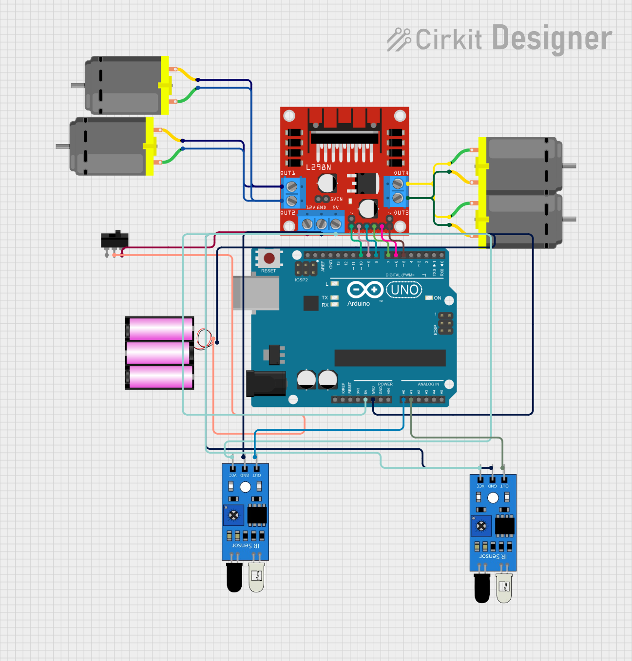
Circuit Documentation
Summary
This circuit is designed to control a set of DC motors using an L298N DC motor driver, which is interfaced with an Arduino UNO microcontroller. The Arduino UNO reads inputs from two IR sensors to determine the motion of the motors (forward, backward, left, right, or stop). A toggle switch is used to control the power supply from a 12V battery to the motor driver. The motors are expected to respond to the sensor inputs for navigation purposes.
Component List
DC Motor
- Description: A standard DC motor used for converting electrical energy into mechanical rotation.
- Pins: pin 1 (Motor positive), pin 2 (Motor negative)
L298N DC Motor Driver
- Description: A motor driver module capable of driving two DC motors or one stepper motor.
- Pins: OUT1, OUT2, OUT3, OUT4 (Motor outputs), 12V (Power input), GND (Ground), 5V (5V output/input), ENA, ENB (Enable pins for motors), IN1, IN2, IN3, IN4 (Control inputs)
Toggle Switch
- Description: A switch used to control the flow of electricity in a circuit.
- Pins: L1, COM (Common), L2
Battery 12V
- Description: A 12V battery providing the power source for the circuit.
- Pins: + (Positive), - (Negative)
Arduino UNO
- Description: A microcontroller board based on the ATmega328P, used for controlling the logic of the circuit.
- Pins: Digital I/O pins (D0-D13), Analog input pins (A0-A5), Power pins (3.3V, 5V, GND, Vin), I2C pins (SCL, SDA), SPI pins (on ICSP header), Reset
IR Sensor
- Description: An infrared sensor used for detecting obstacles or making simple object sensors.
- Pins: out (Signal output), gnd (Ground), vcc (Power input)
Wiring Details
DC Motors
- Motor 1: Connected to OUT1 and OUT2 on the L298N motor driver.
- Motor 2: Connected to OUT3 and OUT4 on the L298N motor driver.
L298N DC Motor Driver
- Power: 12V pin connected to the Toggle Switch.
- Ground: GND pin connected to the common ground net.
- Control Inputs: IN1, IN2, IN3, and IN4 connected to digital pins D9, D8, D7, and D6 on the Arduino UNO respectively.
- Enable Pins: ENA and ENB connected to digital pins D10 and D5 on the Arduino UNO respectively.
Toggle Switch
- COM: Connected to the positive terminal of the 12V battery.
- L2: Connected to the 12V input on the L298N motor driver.
Battery 12V
- Positive Terminal: Connected to the COM pin of the Toggle Switch.
- Negative Terminal: Connected to the common ground net.
Arduino UNO
- Ground: Connected to the common ground net.
- 5V: Connected to the 5V pin on the L298N motor driver and VCC pins of the IR sensors.
- Digital Pins: D10, D9, D8, D7, D6 connected to the L298N motor driver.
- Analog Pins: A0 and A1 connected to the output pins of the IR sensors.
IR Sensors
- VCC: Connected to the 5V output from the Arduino UNO.
- GND: Connected to the common ground net.
- OUT: Connected to analog pins A0 and A1 on the Arduino UNO.
Documented Code
#define in1 9
#define in2 8
#define in3 7
#define in4 6
#define enA 10
#define enB 5
int M1_Speed = 80; // speed of motor 1
int M2_Speed = 80; // speed of motor 2
int LeftRotationSpeed = 250; // Left Rotation Speed
int RightRotationSpeed = 250; // Right Rotation Speed

void setup() {
  pinMode(in1, OUTPUT);
  pinMode(in2, OUTPUT);
  pinMode(in3, OUTPUT);
  pinMode(in4, OUTPUT);
  pinMode(enA, OUTPUT);
  pinMode(enB, OUTPUT);
  pinMode(A0, INPUT); // initialize Left sensor as an input
  pinMode(A1, INPUT); // initialize Right sensor as an input
}

void loop() {
  int LEFT_SENSOR = digitalRead(A0);
  int RIGHT_SENSOR = digitalRead(A1);
  if (RIGHT_SENSOR == 0 && LEFT_SENSOR == 0) {
    forward(); //FORWARD
  } else if (RIGHT_SENSOR == 0 && LEFT_SENSOR == 1) {
    right(); //Move Right
  } else if (RIGHT_SENSOR == 1 && LEFT_SENSOR == 0) {
    left(); //Move Left
  } else if (RIGHT_SENSOR == 1 && LEFT_SENSOR == 1) {
    Stop(); //STOP
  }
}

void forward() {
  digitalWrite(in1, HIGH);
  digitalWrite(in2, LOW);
  digitalWrite(in3, HIGH);
  digitalWrite(in4, LOW);
  analogWrite(enA, M1_Speed);
  analogWrite(enB, M2_Speed);
}

void backward() {
  digitalWrite(in1, LOW);
  digitalWrite(in2, HIGH);
  digitalWrite(in3, LOW);
  digitalWrite(in4, HIGH);
  analogWrite(enA, M1_Speed);
  analogWrite(enB, M2_Speed);
}

void right() {
  digitalWrite(in1, LOW);
  digitalWrite(in2, HIGH);
  digitalWrite(in3, HIGH);
  digitalWrite(in4, LOW);
  analogWrite(enA, LeftRotationSpeed);
  analogWrite(enB, RightRotationSpeed);
}

void left() {
  digitalWrite(in1, HIGH);
  digitalWrite(in2, LOW);
  digitalWrite(in3, LOW);
  digitalWrite(in4, HIGH);
  analogWrite(enA, LeftRotationSpeed);
  analogWrite(enB, RightRotationSpeed);
}

void Stop() {
  digitalWrite(in1, LOW);
  digitalWrite(in2, LOW);
  digitalWrite(in3, LOW);
  digitalWrite(in4, LOW);
}
This code is responsible for controlling the DC motors through the L298N motor driver based on the input from the IR sensors. The forward, backward, right, left, and Stop functions are used to control the direction of the motors. The setup function initializes the pins, and the loop function reads the sensor inputs to determine the direction of motion.