
Arduino Uno-Based Water Level Monitoring System with LED Indicators and Buzzer Alert
View and Edit Project In Cirkit Designer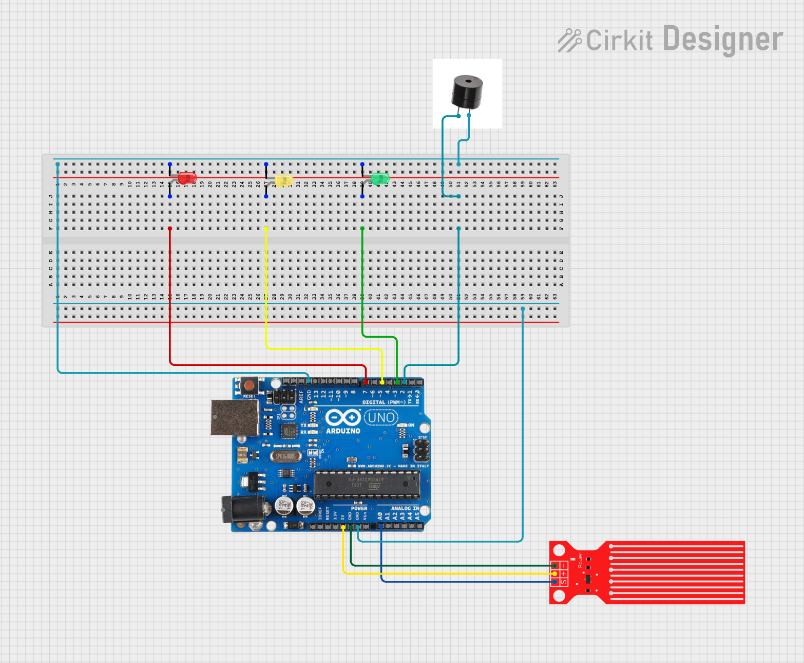
Circuit Documentation
Summary
This circuit is designed to monitor water levels using a water level sensor and provide visual and auditory feedback through LEDs and a buzzer. The system is controlled by an Arduino Uno R3 microcontroller, which reads the sensor data and activates the LEDs and buzzer based on predefined thresholds.
Component List
Arduino Uno R3
- Description: A microcontroller board based on the ATmega328P.
- Pins: D8, D9, D10, D11, D12, D13, GND, AREF, SDA, SCL, D0/RX, D1/Tx, D2, D3, D4, D5, 6, D7, A5/SCL, A4/SDA, A3, A2, A1, A0, Vin, 5V, 3.3V, RESET, IOREF, NONE, USB Jack, Power Jack
Water Level Sensor
- Description: A sensor used to measure the water level.
- Pins: SIG, VCC, GND
LED: Two Pin (red)
- Description: A red LED with two pins.
- Pins: cathode, anode
LED: Two Pin (yellow)
- Description: A yellow LED with two pins.
- Pins: cathode, anode
LED: Two Pin (green)
- Description: A green LED with two pins.
- Pins: cathode, anode
Buzzer
- Description: A buzzer used for auditory feedback.
- Pins: +, GND
Wiring Details
Arduino Uno R3
- D7: Connected to the anode of the red LED.
- D5: Connected to the anode of the yellow LED.
- D3: Connected to the anode of the green LED.
- D2: Connected to the + pin of the buzzer.
- GND: Connected to the cathode of the red LED, yellow LED, green LED, and the GND pin of the buzzer.
- A0: Connected to the SIG pin of the water level sensor.
- 5V: Connected to the VCC pin of the water level sensor.
- GND: Connected to the GND pin of the water level sensor.
Water Level Sensor
- SIG: Connected to A0 on the Arduino Uno R3.
- VCC: Connected to 5V on the Arduino Uno R3.
- GND: Connected to GND on the Arduino Uno R3.
LED: Two Pin (red)
- anode: Connected to D7 on the Arduino Uno R3.
- cathode: Connected to GND on the Arduino Uno R3.
LED: Two Pin (yellow)
- anode: Connected to D5 on the Arduino Uno R3.
- cathode: Connected to GND on the Arduino Uno R3.
LED: Two Pin (green)
- anode: Connected to D3 on the Arduino Uno R3.
- cathode: Connected to GND on the Arduino Uno R3.
Buzzer
- +: Connected to D2 on the Arduino Uno R3.
- GND: Connected to GND on the Arduino Uno R3.
Code Documentation
Arduino Code
const int analogInPin = A0;
int sensorValue = 0;

// Buzzer pin
const int buzzerPin = 2;

// Timing variables
unsigned long previousMillis = 0;
const long interval = 500; // Interval for toggling the buzzer (in milliseconds)
bool buzzerState = LOW; // Current state of the buzzer

void setup() {
  // Declare pin to be an output:
  pinMode(buzzerPin, OUTPUT);
  pinMode(3, OUTPUT);
  pinMode(4, OUTPUT);
  pinMode(5, OUTPUT);
  pinMode(7, OUTPUT);
  pinMode(8, OUTPUT);
  pinMode(9, OUTPUT);
  Serial.begin(9600);
}

// The loop routine runs over and over again forever:
void loop() {
  sensorValue = analogRead(analogInPin);
  Serial.print("sensor = ");
  Serial.print(sensorValue);
  Serial.print("\n");

  // Control other outputs based on sensor value
  if ((sensorValue >= 200) && (sensorValue <= 400)) {
    digitalWrite(3, HIGH);
    digitalWrite(4, HIGH);
    digitalWrite(5, LOW);
    digitalWrite(7, LOW);
    digitalWrite(8, LOW);
    digitalWrite(9, LOW);
  } else if ((sensorValue >= 401) && (sensorValue <= 500)) {
    digitalWrite(5, HIGH);
    digitalWrite(7, HIGH);
    digitalWrite(3, HIGH);
    digitalWrite(4, HIGH);
    digitalWrite(8, LOW);
    digitalWrite(9, LOW);
  } else if ((sensorValue >= 501) && (sensorValue <= 1000)) {
    digitalWrite(8, HIGH);
    digitalWrite(9, HIGH);
    digitalWrite(3, HIGH);
    digitalWrite(4, HIGH);
    digitalWrite(5, HIGH);
    digitalWrite(7, HIGH);
  } else {
    // Turn off all outputs if sensor value is out of range
    digitalWrite(3, LOW);
    digitalWrite(4, LOW);
    digitalWrite(5, LOW);
    digitalWrite(7, LOW);
    digitalWrite(8, LOW);
    digitalWrite(9, LOW);
    digitalWrite(buzzerPin, LOW); // Ensure buzzer is off
    return; // Exit the loop early
  }

  // Check if both LEDs (8 and 9) are HIGH to control the buzzer
  if (digitalRead(8) == HIGH && digitalRead(9) == HIGH) {
    // Check the time to toggle the buzzer
    unsigned long currentMillis = millis();
    if (currentMillis - previousMillis >= interval) {
      previousMillis = currentMillis; // Save the last time you toggled the buzzer
      buzzerState = !buzzerState; // Toggle the buzzer state
      digitalWrite(buzzerPin, buzzerState); // Set the buzzer to the new state
    }
  } else {
    // If either LED is off, ensure the buzzer is off
    digitalWrite(buzzerPin, LOW);
  }
}
This code reads the water level sensor value and controls the LEDs and buzzer based on the sensor readings. The buzzer toggles on and off at a set interval when both LEDs (connected to pins 8 and 9) are HIGH.