ESP32-Based Smart Weather Station with LCD Display and Servo Control
Circuit Documentation
Summary
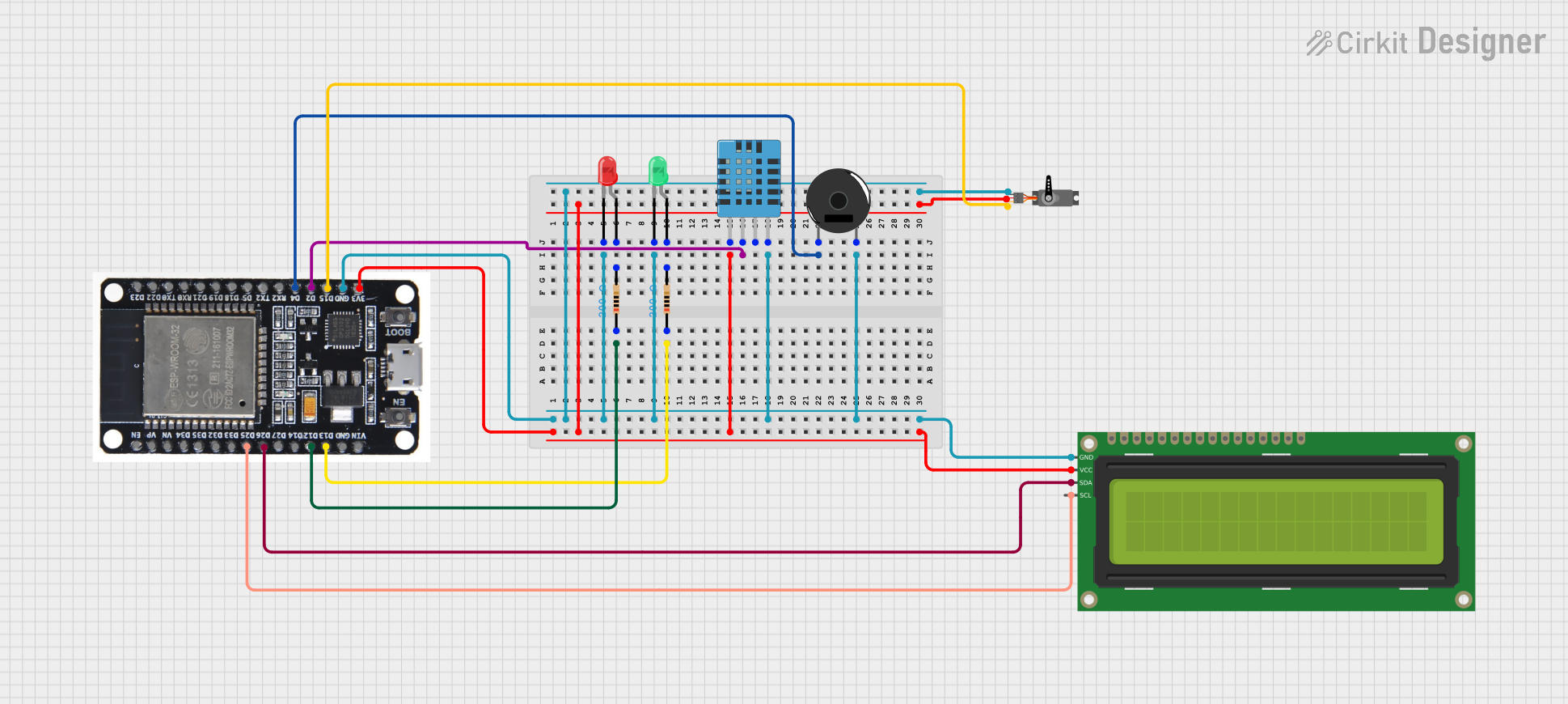
This document provides a detailed overview of a circuit that includes various components such as resistors, LEDs, a DHT11 humidity and temperature sensor, an ESP32 microcontroller, a piezo buzzer, a 16x2 I2C LCD, and a servo motor. The circuit is designed to interface these components with the ESP32 microcontroller to perform various functions such as sensing temperature and humidity, displaying information on an LCD, and controlling a servo motor and LEDs.
Component List
Resistor
- Description: A resistor with a resistance of 200 Ohms.
- Pins: pin1, pin2
DHT11 Humidity and Temperature Sensor
- Description: A sensor used to measure humidity and temperature.
- Pins: VDD, DATA, NULL, GND
ESP32
- Description: A microcontroller with multiple GPIO pins and built-in Wi-Fi and Bluetooth capabilities.
- Pins: EN, VP, VN, D34, D35, D32, D33, D25, D26, D27, D14, D12, D13, GND, VIN, 3V3, D15, D2, D4, RX2, TX2, D5, D18, D19, D21, RX0, TX0, D22, D23, BOOT
LED: Two Pin (red)
- Description: A red LED.
- Pins: cathode, anode
LED: Two Pin (green)
- Description: A green LED.
- Pins: cathode, anode
Piezo Buzzer
- Description: A piezoelectric buzzer used for sound output.
- Pins: pin 1, pin 2
16x2 I2C LCD
- Description: A 16x2 character LCD with I2C interface.
- Pins: GND, VCC, SDA, SCL
Servo
- Description: A servo motor used for precise control of angular position.
- Pins: GND, VCC, PWM
Wiring Details
Resistor
Resistor 1
- pin1: Connected to ESP32 pin D12
- pin2: Connected to the anode of the red LED
Resistor 2
- pin1: Connected to ESP32 pin D13
- pin2: Connected to the anode of the green LED
DHT11 Humidity and Temperature Sensor
- VDD: Connected to ESP32 pin 3V3
- DATA: Connected to ESP32 pin D2
- GND: Connected to ESP32 pin GND
ESP32
- GND: Connected to the GND pins of the DHT11 sensor, red LED, green LED, piezo buzzer, 16x2 I2C LCD, and servo motor
- 3V3: Connected to the VDD pin of the DHT11 sensor, VCC pin of the 16x2 I2C LCD, and VCC pin of the servo motor
- D12: Connected to pin1 of Resistor 1
- D13: Connected to pin1 of Resistor 2
- D2: Connected to the DATA pin of the DHT11 sensor
- D4: Connected to pin 1 of the piezo buzzer
- D25: Connected to the SCL pin of the 16x2 I2C LCD
- D26: Connected to the SDA pin of the 16x2 I2C LCD
- D15: Connected to the PWM pin of the servo motor
LED: Two Pin (red)
- cathode: Connected to ESP32 pin GND
- anode: Connected to pin2 of Resistor 1
LED: Two Pin (green)
- cathode: Connected to ESP32 pin GND
- anode: Connected to pin2 of Resistor 2
Piezo Buzzer
- pin 1: Connected to ESP32 pin D4
- pin 2: Connected to ESP32 pin GND
16x2 I2C LCD
- GND: Connected to ESP32 pin GND
- VCC: Connected to ESP32 pin 3V3
- SDA: Connected to ESP32 pin D26
- SCL: Connected to ESP32 pin D25
Servo
- GND: Connected to ESP32 pin GND
- VCC: Connected to ESP32 pin 3V3
- PWM: Connected to ESP32 pin D15
Code
No code is provided for this circuit.
This document provides a comprehensive overview of the circuit, including a summary, component list, wiring details, and code section. Each component is described in detail, and the wiring connections are clearly specified to ensure proper assembly and functionality of the circuit.