
Arduino-Controlled Line Following Robot with H-Bridge Motor Driver and IR Sensors
View and Edit Project In Cirkit Designer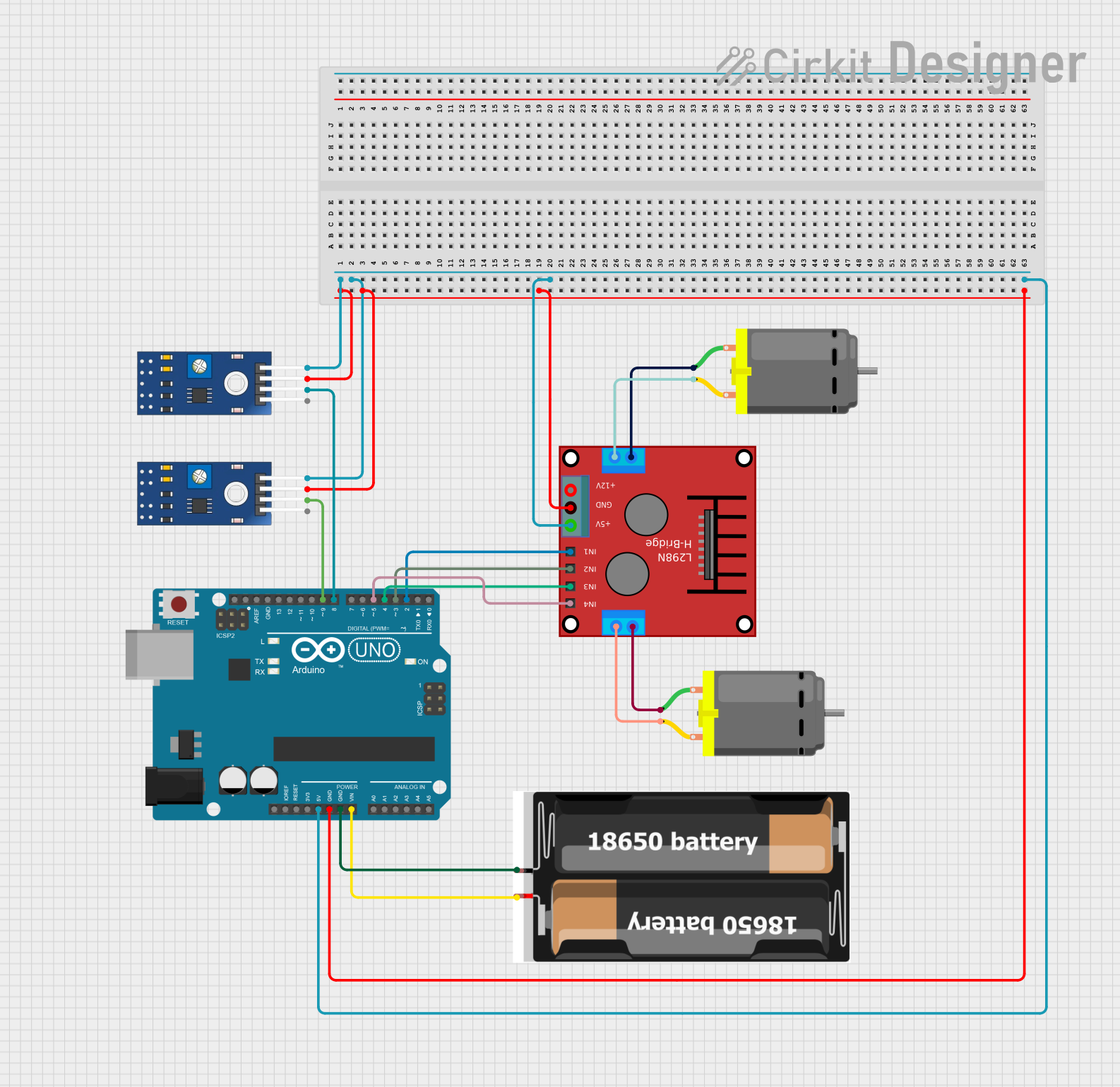
Circuit Documentation
Summary
The circuit in question is designed to control two DC motors using an H-bridge (ponte h) and is interfaced with an Arduino UNO microcontroller. The system also includes two TCRT 5000 IR sensors for input, which are likely used for line tracking or obstacle detection. The power supply for the circuit is provided by two 18650 batteries connected to the Arduino UNO, which also powers the other components through its voltage regulator.
Component List
Arduino UNO
- Microcontroller board based on the ATmega328P
- Provides digital I/O pins, analog inputs, and various power outputs
- Used for controlling the H-bridge and reading sensor inputs
Ponte H
- An H-bridge circuit used for controlling the direction and speed of DC motors
- Receives control signals from the Arduino UNO
TCRT 5000 IR SENSOR (x2)
- Infrared reflective sensors
- Used for detecting the presence of an object or changes in a surface
DC Motor (x2)
- Electric motors that convert electrical energy into mechanical rotation
- Controlled by the H-bridge for direction and possibly speed
2x 18650 Battery Pack
- Provides power to the Arduino UNO and, through it, to other components in the circuit
Wiring Details
Arduino UNO
5VandGNDare connected to the corresponding pins on the ponte H and both TCRT 5000 IR sensors to provide power.D4is connected toIN3on the ponte H.D2is connected toIN1on the ponte H.D3is connected toIN2on the ponte H.D5is connected toIN4on the ponte H.GNDis connected to the negative terminal of the 18650 battery pack.Vinis connected to the positive terminal of the 18650 battery pack.D9is connected to theDOpin of one TCRT 5000 IR sensor.D8is connected to theDOpin of the other TCRT 5000 IR sensor.
Ponte H
OUT4-Motor2andOUT3-Motor2are connected to the two pins of one DC motor.OUT2-Motor1andOUT1-Motor1are connected to the two pins of the other DC motor.5VandGNDare used to power the ponte H from the Arduino UNO.IN1,IN2,IN3, andIN4receive control signals from the Arduino UNO.
TCRT 5000 IR SENSOR
- Both sensors have their
VCCconnected to5VandGNDtoGNDon the Arduino UNO for power. - The
DOpins are connected to digital pinsD8andD9on the Arduino UNO for digital output signals.
DC Motor
- Each motor has two pins connected to the ponte H for control of the motor's direction.
2x 18650 Battery Pack
vccis connected to theVinpin on the Arduino UNO to supply power.gndis connected to theGNDpin on the Arduino UNO to complete the circuit.
Documented Code
// *** DECLARAMOS LAS VARIABLES QUE VAMOS A UTILIZAR ***
static int PinIN1 = 2;
static int PinIN2 = 3;
static int PinIN3 = 4;
static int PinIN4 = 5;
static int Pin_sensor1 = 8;   // Con este pin recogemos las señales del sensor
static int Pin_sensor2 = 9;   // Con este pin recogemos las señales del sensor

void setup() {
  Serial.begin(9600);               //iniciamos las comunicaciones con el puerto serie para el monitor serie
  pinMode(PinIN1, OUTPUT);
  pinMode(PinIN2, OUTPUT);
  pinMode(PinIN3, OUTPUT);
  pinMode(PinIN4, OUTPUT);
  pinMode(Pin_sensor1, INPUT);       //definimos el pin que vamos a utilizar como entrada para el sensor izquierdo
  pinMode(Pin_sensor2, INPUT);       //definimos el pin que vamos a utilizar como entrada para el sensor derecho
}

void loop() {

  int value1 = 0;                        // Variable temporal que usaremos para recoger la señal del sensor izquierdo
  int value2 = 0;                        // Variable temporal que usaremos para recoger la señal del sensor derecho
  value1 = digitalRead(Pin_sensor1);     // lectura digital de pin del sensor1
  value2 = digitalRead(Pin_sensor2);     // lectura digital de pin del sensor2

  if (value1 == LOW && value2 == LOW)
  {
    Serial.println("adelante");
    MotorAdelante();
  }

  if (value1 == HIGH && value2 == HIGH)
  {
    Serial.println("detenido");
    MotorStop();
  }

   if (value1 == HIGH && value2 == LOW) // Si el sensor izuierdo detecta una zona oscura
    {
     Serial.println("izquierda");
     MotorIzquierda();
    }

   if (value2 == HIGH && value1 == LOW) // Si el sensor derecho detecta una zona oscura
    {
     Serial.println("derecha");
     MotorDerecha();
    }

  delay(20);                             // Hacemos una pausa en milisegundos, de forma que leemos el sensor cada dicho tiempo
}

  void MotorIzquierda()
  {
  digitalWrite (PinIN1, HIGH);            // Motor Izquierdo atras
  digitalWrite (PinIN2, LOW);
  digitalWrite (PinIN3, HIGH);            // Motor Derecho adelante
  digitalWrite (PinIN4, LOW);
  }

  void MotorDerecha()
  {
  digitalWrite (PinIN1, LOW);             // Motor Izquierdo adelante
  digitalWrite (PinIN2, HIGH);
  digitalWrite (PinIN3, LOW);             // Motor Derecho atras
  digitalWrite (PinIN4, HIGH);
  }

  void MotorAdelante()
  {
  digitalWrite (PinIN1, LOW);             // Motor Izquierdo adelante
  digitalWrite (PinIN2, HIGH);
  digitalWrite (PinIN3, HIGH);            // Motor Derecho adelante
  digitalWrite (PinIN4, LOW);
  }

  void MotorStop()
  {
  digitalWrite (PinIN1, LOW);             // Motor Izquierdo detenido
  digitalWrite (PinIN2, LOW);
  digitalWrite (PinIN3, LOW);             // Motor Derecho detenido
  digitalWrite (PinIN4, LOW);

  }
The code provided is an Arduino sketch that controls the motors based on the input from the TCRT 5000 IR sensors. The MotorAdelante, MotorStop, MotorIzquierda, and MotorDerecha functions control the motors' movements to go forward, stop, turn left, and turn right, respectively. The loop function reads the sensor values and determines the movement of the motors based on the sensor inputs.