
Arduino RFID Access Control System with Servo Lock and LED Indicators
View and Edit Project In Cirkit Designer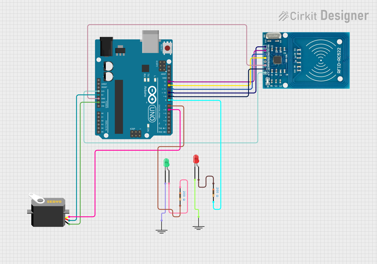
Circuit Documentation
Summary
This circuit is an RFID-based access control system using an Arduino UNO. It includes an RFID reader to scan tags, a servo motor to lock/unlock a mechanism, and two LEDs (red and green) to indicate access status. The system checks if the scanned RFID tag matches a predefined authorized tag.
Component List
LED: Two Pin (red)
- Description: A red LED used to indicate access denial.
- Pins: Cathode, Anode
Arduino UNO
- Description: The main microcontroller used to control the circuit.
- Pins: UNUSED, IOREF, Reset, 3.3V, 5V, GND, Vin, A0, A1, A2, A3, A4, A5, SCL, SDA, AREF, D13, D12, D11, D10, D9, D8, D7, D6, D5, D4, D3, D2, D1, D0
Servo
- Description: A servo motor used to lock/unlock the mechanism.
- Pins: GND, VCC, Pulse
Resistor (200 Ohms)
- Description: A resistor used to limit current.
- Pins: Pin1, Pin2
- Properties: Resistance: 200 Ohms
LED: Two Pin (green)
- Description: A green LED used to indicate access granted.
- Pins: Cathode, Anode
RFID-RC522
- Description: An RFID reader module used to scan RFID tags.
- Pins: VCC (3.3V), RST, GND, IRQ, MISO, MOSI, SCK, SDA
GND
- Description: Ground connection.
- Pins: GND
Wiring Details
LED: Two Pin (red)
- Cathode connected to GND
- Anode connected to Pin1 of a 200 Ohm resistor
Arduino UNO
- 3.3V connected to VCC (3.3V) of RFID-RC522
- 5V connected to VCC of Servo
- GND connected to GND of RFID-RC522 and GND of Servo
- D13 connected to SCK of RFID-RC522
- D12 connected to MISO of RFID-RC522
- D11 connected to MOSI of RFID-RC522
- D10 connected to SDA of RFID-RC522
- D9 connected to RST of RFID-RC522
- D8 connected to Pin2 of a 200 Ohm resistor
- D7 connected to Pin2 of another 200 Ohm resistor
- D6 connected to Pulse of Servo
Servo
- VCC connected to 5V of Arduino UNO
- GND connected to GND of Arduino UNO
- Pulse connected to D6 of Arduino UNO
Resistor (200 Ohms)
- Pin1 connected to Anode of red LED
- Pin2 connected to D8 of Arduino UNO
LED: Two Pin (green)
- Anode connected to Pin1 of another 200 Ohm resistor
- Cathode connected to GND
RFID-RC522
- VCC (3.3V) connected to 3.3V of Arduino UNO
- RST connected to D9 of Arduino UNO
- GND connected to GND of Arduino UNO
- SCK connected to D13 of Arduino UNO
- MISO connected to D12 of Arduino UNO
- MOSI connected to D11 of Arduino UNO
- SDA connected to D10 of Arduino UNO
GND
- GND connected to Cathode of green LED
Code Documentation
Arduino UNO Code
/*
 * This Arduino sketch controls an RFID-based access system.
 * It uses an RFID reader to scan tags and a servo motor to
 * lock/unlock a mechanism. Green and red LEDs indicate access
 * status. The system checks if the scanned RFID tag matches
 * a predefined authorized tag.
 */

#include <SPI.h>
#include <MFRC522.h>
#include <Servo.h>

#define RST_PIN 9
#define SS_PIN 10

MFRC522 rfid(SS_PIN, RST_PIN);
Servo serrure;

String tagAutorise = "AB CD EF 12"; // Replace with your tag UID

void setup() {
  Serial.begin(9600);
  SPI.begin();
  rfid.PCD_Init();
  serrure.attach(6); // Servo pin
  serrure.write(0);  // Lock

  pinMode(7, OUTPUT); // Green LED
  pinMode(8, OUTPUT); // Red LED
  digitalWrite(7, LOW);
  digitalWrite(8, LOW);

  Serial.println("Ready to scan a tag.");
}

void loop() {
  if (!rfid.PICC_IsNewCardPresent() || !rfid.PICC_ReadCardSerial()) {
    return;
  }

  String uid = "";
  for (byte i = 0; i < rfid.uid.size; i++) {
    uid += String(rfid.uid.uidByte[i], HEX);
    if (i < rfid.uid.size - 1) uid += " ";
  }
  uid.toUpperCase();
  Serial.println("UID tag: " + uid);

  if (uid == tagAutorise) {
    digitalWrite(7, HIGH); // Green LED on
    digitalWrite(8, LOW);  // Red LED off
    Serial.println("Access granted!");
    serrure.write(90); // Unlock
    delay(5000);       // Wait before locking
    serrure.write(0);  // Lock
  } else {
    digitalWrite(7, LOW);  // Green LED off
    digitalWrite(8, HIGH); // Red LED on
    Serial.println("Access denied!");
    delay(2000);
  }

  rfid.PICC_HaltA();
}
GND Code
void setup() {
  // put your setup code here, to run once:

}

void loop() {
  // put your main code here, to run repeatedly:

}
This documentation provides a comprehensive overview of the circuit, including a summary, component list, wiring details, and the code used in the Arduino UNO.