
Arduino-Based Underground Cable Fault Detector with LCD Display and Buzzer Alert
View and Edit Project In Cirkit Designer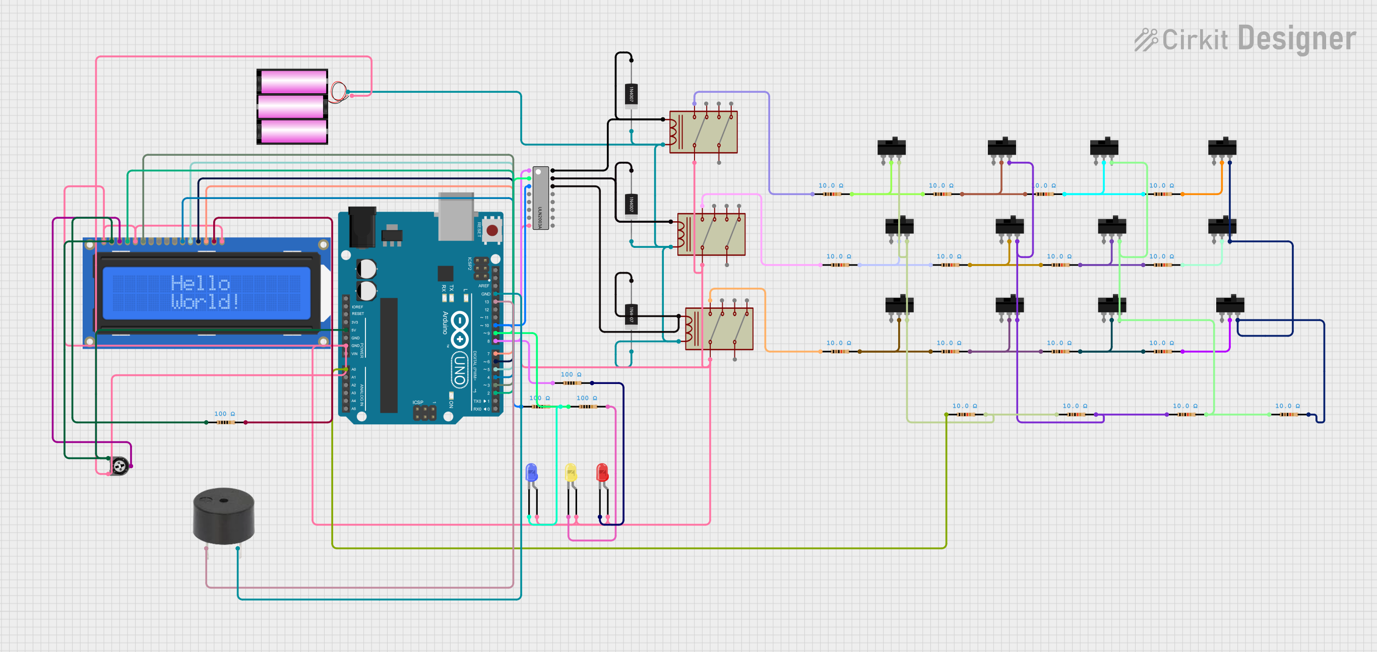
Circuit Documentation
Summary
This circuit is an underground cable fault detector using an Arduino UNO microcontroller. It reads sensor values to detect faults in underground cables, controls three relays, and displays fault information on an LCD. A buzzer is used to alert when a fault is detected.
Component List
Battery 12V
- Pins: +, -
- Description: Provides power to the circuit.
- Purpose: Power source.
Buzzer
- Pins: PIN, GND
- Description: Emits sound when a fault is detected.
- Purpose: Alert mechanism.
LED: Two Pin (blue)
- Pins: Cathode, Anode
- Description: Blue LED.
- Purpose: Visual indicator.
LED: Two Pin (red)
- Pins: Cathode, Anode
- Description: Red LED.
- Purpose: Visual indicator.
LED: Two Pin (yellow)
- Pins: Cathode, Anode
- Description: Yellow LED.
- Purpose: Visual indicator.
Adafruit Standard LCD 16x2 white on blue
- Pins: VSS, VDD, V0, RS, R/W, E, DB0, DB1, DB2, DB3, DB4, DB5, DB6, DB7, LED+, LED-
- Description: 16x2 character LCD.
- Purpose: Display fault information.
Toggle Switch
- Pins: L1, COM, L2
- Description: Mechanical switch.
- Purpose: User input.
Resistor (10 Ohms)
- Pins: pin1, pin2
- Description: 10 Ohm resistor.
- Purpose: Current limiting.
Resistor (100 Ohms)
- Pins: pin1, pin2
- Description: 100 Ohm resistor.
- Purpose: Current limiting.
Trimmer Potentiometer (10k Ohms)
- Pins: leg1, wiper, leg2
- Description: Adjustable resistor.
- Purpose: Adjust LCD contrast.
Relay
- Pins: Common 1, Common 2, Coil, NO 1, NC 1, NO 2, NC 2
- Description: Electromechanical switch.
- Purpose: Control high power devices.
1N4007 Rectifier Diode
- Pins: Cathode, Anode
- Description: Rectifier diode.
- Purpose: Protects against reverse voltage.
Arduino UNO
- Pins: UNUSED, IOREF, Reset, 3.3V, 5V, GND, Vin, A0, A1, A2, A3, A4, A5, SCL, SDA, AREF, D13, D12, D11, D10, D9, D8, D7, D6, D5, D4, D3, D2, D1, D0
- Description: Microcontroller board.
- Purpose: Control and processing unit.
ULN2003A
- Pins: Input 1, Input 2, Input 3, Input 4, Input 5, Input 6, Input 7, GND, Output 1, Output 2, Output 3, Output 4, Output 5, Output 6, Output 7, COM
- Description: Darlington transistor array.
- Purpose: Drive relays.
Wiring Details
Battery 12V
- +: Connected to the Cathode of 1N4007 Rectifier Diodes and Coils of Relays.
- -: Connected to GND of Arduino UNO, VSS, LED-, and R/W of LCD, anodes of LEDs, Common 1 of Relays, and leg2 of Trimmer Potentiometer.
Buzzer
- PIN: Connected to D13 of Arduino UNO.
- GND: Connected to GND of Arduino UNO.
LED: Two Pin (blue)
- Cathode: Connected to pin2 of a 100 Ohm Resistor.
- Anode: Connected to GND.
LED: Two Pin (red)
- Cathode: Connected to pin2 of a 100 Ohm Resistor.
- Anode: Connected to GND.
LED: Two Pin (yellow)
- Cathode: Connected to pin2 of a 100 Ohm Resistor.
- Anode: Connected to GND.
Adafruit Standard LCD 16x2 white on blue
- VSS: Connected to GND.
- VDD: Connected to 5V of Arduino UNO.
- V0: Connected to wiper of Trimmer Potentiometer.
- RS: Connected to D2 of Arduino UNO.
- R/W: Connected to GND.
- E: Connected to D3 of Arduino UNO.
- DB4: Connected to D4 of Arduino UNO.
- DB5: Connected to D5 of Arduino UNO.
- DB6: Connected to D6 of Arduino UNO.
- DB7: Connected to D7 of Arduino UNO.
- LED+: Connected to pin2 of a 100 Ohm Resistor.
- LED-: Connected to GND.
Toggle Switch
- COM: Connected to pin2 of a 10 Ohm Resistor.
- L2: Connected to L2 of other Toggle Switches and pin2 of 10 Ohm Resistors.
Resistor (10 Ohms)
- pin1: Connected to various points in the circuit.
- pin2: Connected to COM of Toggle Switches.
Resistor (100 Ohms)
- pin1: Connected to various points in the circuit.
- pin2: Connected to cathodes of LEDs and LED+ of LCD.
Trimmer Potentiometer (10k Ohms)
- leg1: Connected to 5V of Arduino UNO.
- wiper: Connected to V0 of LCD.
- leg2: Connected to GND.
Relay
- Common 1: Connected to GND.
- Coil: Connected to Cathode of 1N4007 Rectifier Diodes and + of Battery 12V.
- NO 1: Connected to pin1 of 10 Ohm Resistors.
1N4007 Rectifier Diode
- Cathode: Connected to Coil of Relays and + of Battery 12V.
- Anode: Connected to Output of ULN2003A.
Arduino UNO
- GND: Connected to GND.
- 5V: Connected to VDD of LCD.
- D2: Connected to RS of LCD.
- D3: Connected to E of LCD.
- D4: Connected to DB4 of LCD.
- D5: Connected to DB5 of LCD.
- D6: Connected to DB6 of LCD.
- D7: Connected to DB7 of LCD.
- D8: Connected to Input 1 of ULN2003A.
- D9: Connected to Input 2 of ULN2003A.
- D10: Connected to Input 3 of ULN2003A.
- D13: Connected to PIN of Buzzer.
- A0: Connected to pin1 of 10 Ohm Resistor.
ULN2003A
- GND: Connected to GND.
- Input 1: Connected to D8 of Arduino UNO.
- Input 2: Connected to D9 of Arduino UNO.
- Input 3: Connected to D10 of Arduino UNO.
- Output 1: Connected to Coil of Relay and Anode of 1N4007 Rectifier Diode.
- Output 2: Connected to Coil of Relay and Anode of 1N4007 Rectifier Diode.
- Output 3: Connected to Coil of Relay and Anode of 1N4007 Rectifier Diode.
Code Documentation
/*
 * Underground Cable Fault Detector using Node MCU ESP8266
 * This code reads sensor values to detect faults in underground cables.
 * It controls three relays and displays fault information on an LCD.
 * The buzzer is used to alert when a fault is detected.
 */

#include <LiquidCrystal.h>

// initialize the library with the numbers of the interface pins
LiquidCrystal lcd(D2, D3, D4, D5, D6, D7);

int sensorPin = A0; // select the input pin for LDR
int sensorValue = 0; // variable to store the value coming from the sensor

void setup() {
  pinMode(D8, OUTPUT); // Relay 1
  pinMode(D9, OUTPUT); // Relay 2
  pinMode(D10