
Arduino-Based Sound-Activated Smart Light with Relay Control
View and Edit Project In Cirkit Designer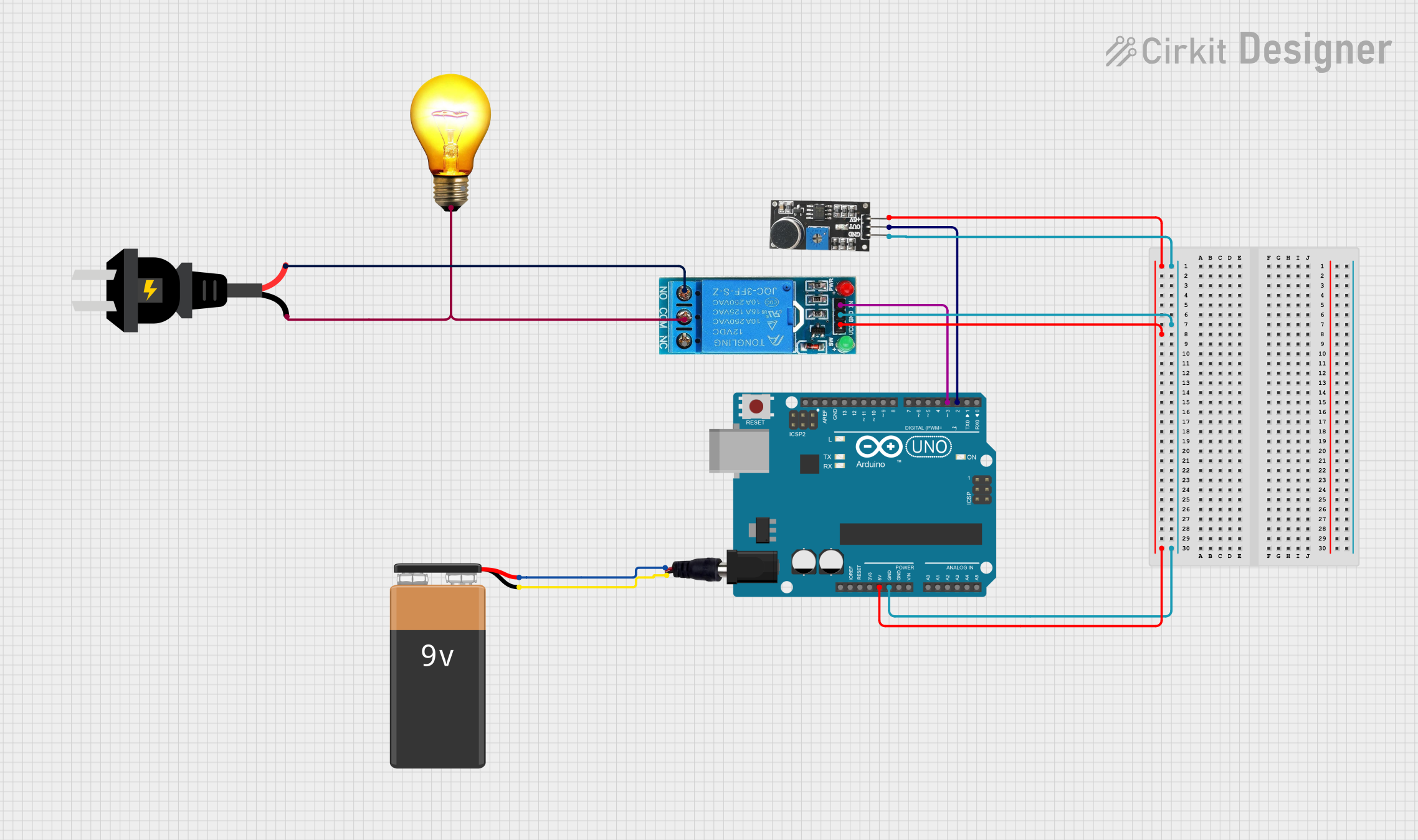
Circuit Documentation
Summary
This circuit is designed to control an AC bulb using a sound sensor and an Arduino UNO. The sound sensor detects sound levels and sends a signal to the Arduino, which then controls a relay to turn the AC bulb on or off. The circuit is powered by a 9V battery connected through a power jack.
Component List
9V Battery
- Description: Provides power to the circuit.
- Pins: -, +
Power Jack
- Description: Connects the 9V battery to the circuit.
- Pins: POSITIF, NEGATIF
AC Source
- Description: Provides AC power to the AC bulb.
- Pins: +, -
Sound Sensor
- Description: Detects sound levels and outputs a signal.
- Pins: 5V +, OUT, GND
Arduino UNO
- Description: Microcontroller that processes the sound sensor signal and controls the relay.
- Pins: UNUSED, IOREF, Reset, 3.3V, 5V, GND, Vin, A0, A1, A2, A3, A4, A5, SCL, SDA, AREF, D13, D12, D11, D10, D9, D8, D7, D6, D5, D4, D3, D2, D1, D0
12V Single Channel Relay
- Description: Switches the AC bulb on or off based on the signal from the Arduino.
- Pins: NC, COM, NO, IN, GND, VCC
AC Bulb
- Description: The load that is controlled by the relay.
- Pins: P, N
Wiring Details
9V Battery
- -: Connected to NEGATIF pin of the Power Jack.
- +: Connected to POSITIF pin of the Power Jack.
Power Jack
- NEGATIF: Connected to - pin of the 9V Battery.
- POSITIF: Connected to + pin of the 9V Battery.
AC Source
- +: Connected to NO pin of the 12V Single Channel Relay.
- -: Connected to COM pin of the 12V Single Channel Relay and P pin of the AC Bulb.
Sound Sensor
- 5V +: Connected to 5V pin of the Arduino UNO and VCC pin of the 12V Single Channel Relay.
- OUT: Connected to D2 pin of the Arduino UNO.
- GND: Connected to GND pin of the Arduino UNO and GND pin of the 12V Single Channel Relay.
Arduino UNO
- 5V: Connected to 5V + pin of the Sound Sensor and VCC pin of the 12V Single Channel Relay.
- GND: Connected to GND pin of the Sound Sensor and GND pin of the 12V Single Channel Relay.
- D2: Connected to OUT pin of the Sound Sensor.
- D3: Connected to IN pin of the 12V Single Channel Relay.
12V Single Channel Relay
- NC: Not connected.
- COM: Connected to - pin of the AC Source and P pin of the AC Bulb.
- NO: Connected to + pin of the AC Source.
- IN: Connected to D3 pin of the Arduino UNO.
- GND: Connected to GND pin of the Sound Sensor and GND pin of the Arduino UNO.
- VCC: Connected to 5V + pin of the Sound Sensor and 5V pin of the Arduino UNO.
AC Bulb
- P: Connected to COM pin of the 12V Single Channel Relay and - pin of the AC Source.
- N: Not connected.
Code Documentation
Arduino UNO Code
void setup() {
  // put your setup code here, to run once:

}

void loop() {
  // put your main code here, to run repeatedly:

}
This code is a basic template for the Arduino UNO. The setup() function is where you initialize your variables and settings, and the loop() function is where the main code runs repeatedly. In this circuit, you would add code to read the sound sensor and control the relay based on the sound levels detected.