
Arduino UNO Solar Tracking System with Light-Dependent Resistors and Servos
View and Edit Project In Cirkit Designer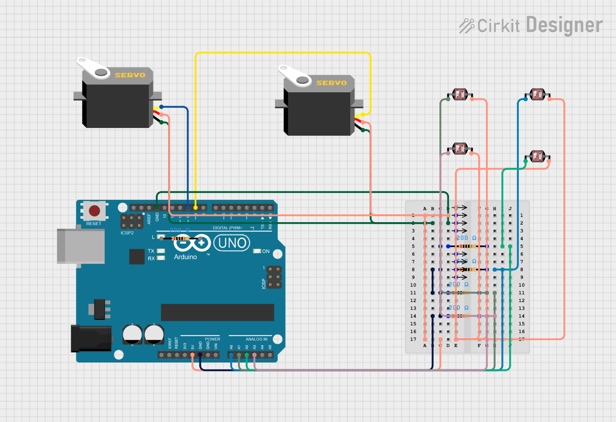
Solar Tracking Energy System Documentation
Summary
This document provides a detailed overview of a solar tracking energy system designed using an Arduino UNO, servos, light-dependent resistors (LDRs), resistors, and Qwiic cables. The system adjusts the position of a solar panel to align with the direction of maximum sunlight using two servos controlled by the Arduino UNO. The LDRs provide feedback on the light intensity from different directions, allowing the system to determine the optimal position for the solar panel.
Component List
Arduino UNO
- Description: A microcontroller board based on the ATmega328P.
- Pins: UNUSED, IOREF, Reset, 3.3V, 5V, GND, Vin, A0, A1, A2, A3, A4, A5, SCL, SDA, AREF, D13, D12, D11, D10, D9, D8, D7, D6, D5, D4, D3, D2, D1, D0
Resistor
- Description: A passive electrical component with a resistance of 200 Ohms.
- Pins: pin1, pin2
- Properties:
- Resistance: 200 Ohms
Servo
- Description: An actuator that allows for precise control of angular position.
- Pins: gnd, vcc, pulse
Photocell (LDR)
- Description: A light-dependent resistor that changes its resistance based on the light intensity.
- Pins: pin 0, pin 1
Qwiic Cable - Breadboard Jumper (4-pin)
- Description: A cable used for connecting Qwiic-enabled devices to a breadboard.
- Pins: GND, 3.3V, SDA, SCL
Wiring Details
Arduino UNO
- 5V: Connected to 3.3V of Qwiic Cable - Breadboard Jumper (4-pin), pin 1 of all Photocells, and vcc of both Servos.
- GND: Connected to SDA of Qwiic Cable - Breadboard Jumper (4-pin), gnd of both Servos, and pin1 of all Resistors.
- A0: Connected to pin2 of a Resistor and pin 0 of a Photocell.
- A1: Connected to pin2 of a Resistor and pin 0 of a Photocell.
- A2: Connected to pin2 of a Resistor and pin 0 of a Photocell.
- A3: Connected to pin2 of a Resistor and pin 0 of a Photocell.
- D10: Connected to pulse of a Servo.
- D9: Connected to pulse of a Servo.
Resistor
- pin1: Connected to GND of Arduino UNO.
- pin2: Connected to A0, A1, A2, and A3 of Arduino UNO and pin 0 of respective Photocells.
Servo
- gnd: Connected to GND of Arduino UNO.
- vcc: Connected to 5V of Arduino UNO.
- pulse: Connected to D10 and D9 of Arduino UNO.
Photocell (LDR)
- pin 0: Connected to pin2 of respective Resistors and A0, A1, A2, and A3 of Arduino UNO.
- pin 1: Connected to 5V of Arduino UNO.
Qwiic Cable - Breadboard Jumper (4-pin)
- 3.3V: Connected to 5V of Arduino UNO.
- SDA: Connected to GND of Arduino UNO.
- GND: Connected to GND of Arduino UNO.
Code Documentation
/*
 * Solar Tracking Energy System
 * This Arduino sketch controls a solar tracking system using two servos and four
 * light-dependent resistors (LDRs). The servos adjust the position of the solar
 * panel to align with the direction of maximum sunlight.
 */

#include <Servo.h>

// Define pins for servos
const int servoPin1 = 10;
const int servoPin2 = 9;

// Define pins for LDRs
const int ldrPin1 = A0;
const int ldrPin2 = A1;
const int ldrPin3 = A2;
const int ldrPin4 = A3;

// Create servo objects
Servo servo1;
Servo servo2;

void setup() {
  // Attach servos to their respective pins
  servo1.attach(servoPin1);
  servo2.attach(servoPin2);

  // Initialize serial communication for debugging
  Serial.begin(9600);
}

void loop() {
  // Read LDR values
  int ldrValue1 = analogRead(ldrPin1);
  int ldrValue2 = analogRead(ldrPin2);
  int ldrValue3 = analogRead(ldrPin3);
  int ldrValue4 = analogRead(ldrPin4);

  // Print LDR values for debugging
  Serial.print("LDR1: ");
  Serial.print(ldrValue1);
  Serial.print(" LDR2: ");
  Serial.print(ldrValue2);
  Serial.print(" LDR3: ");
  Serial.print(ldrValue3);
  Serial.print(" LDR4: ");
  Serial.println(ldrValue4);

  // Calculate average LDR values for horizontal and vertical axes
  int avgHorizontal = (ldrValue1 + ldrValue2) / 2;
  int avgVertical = (ldrValue3 + ldrValue4) / 2;

  // Map LDR values to servo positions
  int servoPos1 = map(avgHorizontal, 0, 1023, 0, 180);
  int servoPos2 = map(avgVertical, 0, 1023, 0, 180);

  // Move servos to calculated positions
  servo1.write(servoPos1);
  servo2.write(servoPos2);

  // Delay for stability
  delay(1000);
}
This code controls the solar tracking system by reading the values from the LDRs, calculating the average light intensity for the horizontal and vertical axes, and adjusting the positions of the servos accordingly. The servos are moved to the positions that align the solar panel with the direction of maximum sunlight.