
Arduino UNO Based RF-Controlled Signal Transmitter with Visual Indicator
View and Edit Project In Cirkit Designer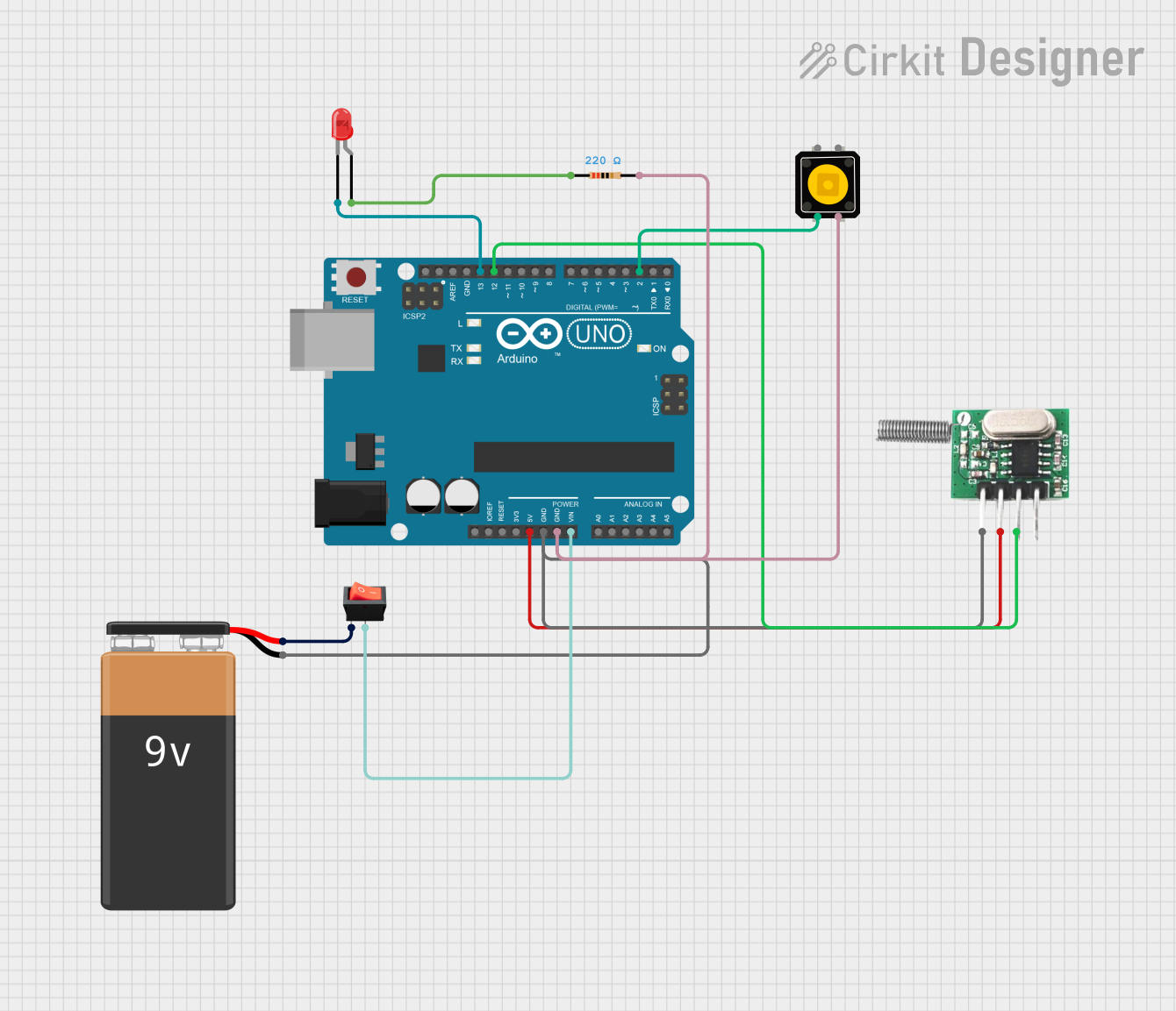
Circuit Documentation
Summary of the Circuit
This circuit is designed to control an RF 433 MHz transmitter and an LED using an Arduino UNO microcontroller. The circuit includes a momentary push button switch that, when pressed, triggers the Arduino to send a signal through the RF transmitter and simultaneously light up an LED. The circuit is powered by a 9V battery, which is controlled by a rocker switch to turn the power supply on and off. A resistor is used in series with the LED to limit the current and protect the LED from damage.
Component List
Arduino UNO
- Microcontroller board based on the ATmega328P
- It has 14 digital input/output pins, 6 analog inputs, a 16 MHz quartz crystal, a USB connection, a power jack, an ICSP header, and a reset button.
9V Battery
- Standard 9V battery used to provide power to the circuit.
Rocker Switch
- A simple on/off switch that controls the connection between the 9V battery and the circuit.
RF 433 MHz Transmitter
- A radio frequency transmitter that operates at 433 MHz for wireless communication.
Momentary Push Button Switch
- A switch that is only active when pressed, used to trigger an event in the circuit.
LED: Two Pin (red)
- A red light-emitting diode that illuminates when powered.
Resistor
- A 220 Ohm resistor used to limit the current through the LED.
Wiring Details
Arduino UNO
5Vpin is connected to the+vepin of the RF 433 MHz Transmitter.GNDpin is connected to the-pin of the 9V Battery,-vepin of the RF 433 MHz Transmitter, andpin2of the Resistor.Vinpin is connected to theoutputpin of the rocker switch.D13pin is connected to thecathodepin of the LED.D12pin is connected to theDatapin of the RF 433 MHz Transmitter.D2pin is connected topin2of the Momentary Push Button Switch.
9V Battery
+pin is connected to theinputpin of the rocker switch.-pin is connected to theGNDpin of the Arduino UNO.
Rocker Switch
inputpin is connected to the+pin of the 9V Battery.outputpin is connected to theVinpin of the Arduino UNO.
RF 433 MHz Transmitter
+vepin is connected to the5Vpin of the Arduino UNO.-vepin is connected to theGNDpin of the Arduino UNO.Datapin is connected to theD12pin of the Arduino UNO.
Momentary Push Button Switch
pin2is connected to theD2pin of the Arduino UNO.pin4is connected to theGNDpin of the Arduino UNO through the Resistor.
LED: Two Pin (red)
anodepin is connected topin1of the Resistor.cathodepin is connected to theD13pin of the Arduino UNO.
Resistor
pin1is connected to theanodepin of the LED.pin2is connected to theGNDpin of the Arduino UNO.
Documented Code
void setup() {
  pinMode(2, INPUT_PULLUP); // Momentary switch connected to D2
  pinMode(12, OUTPUT);      // RF Transmitter Data connected to D12
  pinMode(13, OUTPUT);      // LED connected to D13
}

void loop() {
  if (digitalRead(2) == LOW) { // Check if the momentary switch is pressed
    digitalWrite(12, HIGH);    // Send signal via RF Transmitter
    digitalWrite(13, HIGH);    // Turn on LED
    delay(100);                // Debounce delay
    digitalWrite(12, LOW);     // Stop sending signal
    digitalWrite(13, LOW);     // Turn off LED
  }
}
The code is written for the Arduino UNO microcontroller. In the setup() function, the digital pins are configured: pin 2 as an input with an internal pull-up resistor, and pins 12 and 13 as outputs. The loop() function continuously checks the state of the momentary switch connected to pin 2. When the switch is pressed (logic LOW), the Arduino sends a HIGH signal to the RF transmitter on pin 12 and turns on the LED connected to pin 13. After a short delay to debounce the switch, it turns off both the RF transmitter and the LED.