Cirkit Designer
Your all-in-one circuit design IDE
Home /
Project Documentation
Arduino UNO Controlled LCD Interface with Bluetooth Connectivity and DC Fan Regulation

Circuit Documentation
Summary
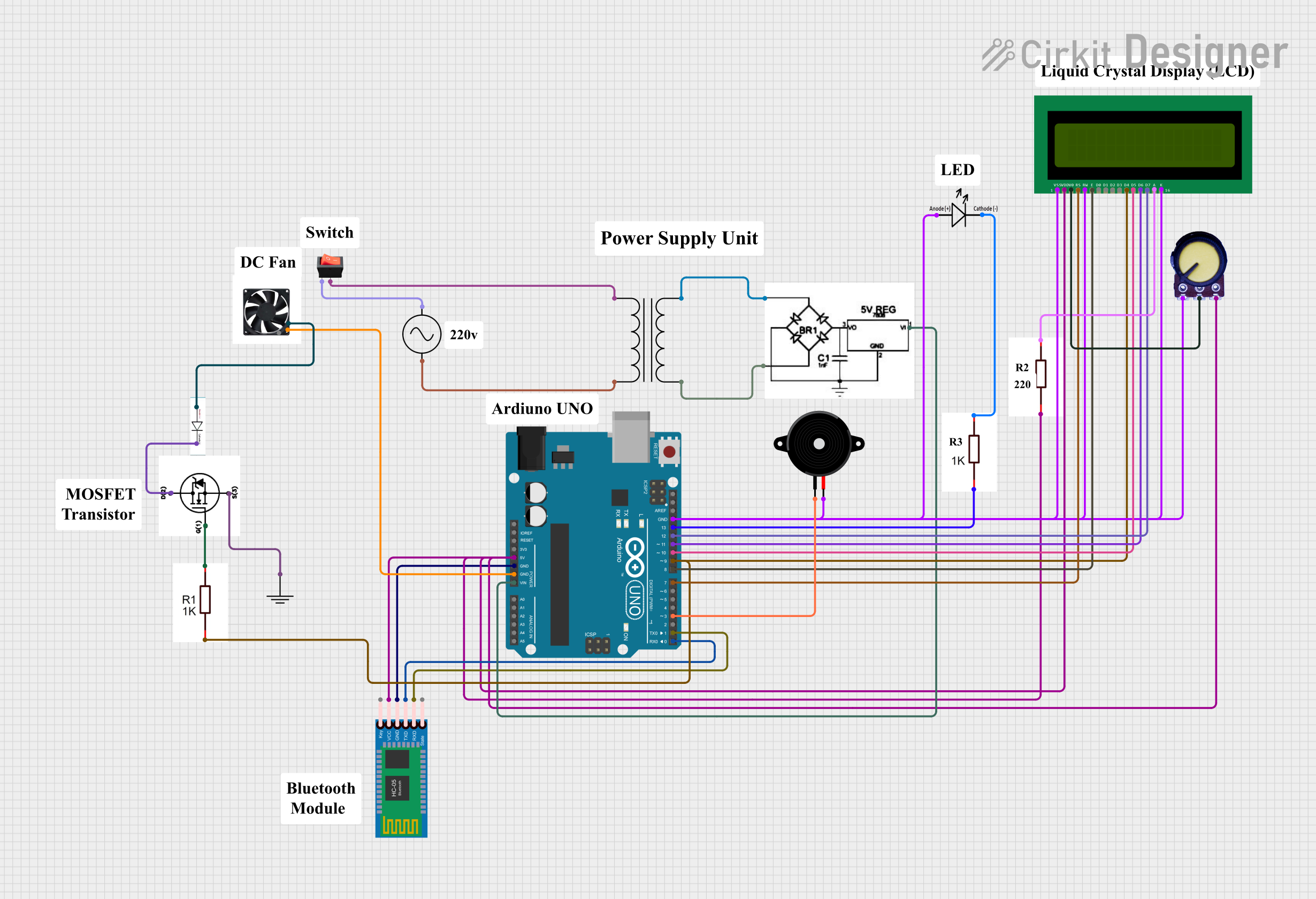
The circuit in question appears to be a microcontroller-based system with various peripherals including a 16X2 LCD display, a power supply, a power transformer, resistors, a rocker switch, an AC supply, a 12v DC fan, a potentiometer, a diode, an N-Channel MOSFET, an LED, a ground reference, an HC-05 Bluetooth module, and a piezo speaker. The microcontroller used is an Arduino UNO, which interfaces with the LCD, Bluetooth module, and piezo speaker, and controls an LED and a DC fan through a MOSFET. The power supply is managed by a transformer and a switch, and the voltage levels for the LCD are adjusted using a potentiometer.
Component List
Power Supply
- Provides the required DC voltage to the circuit.
Power Transformer
- Steps down or steps up the AC voltage.
1k Ohms Resistor
- Limits current or divides voltage in the circuit.
16X2 LCD
- A display module for showing information.
Arduino UNO
- The main microcontroller board for controlling the circuit.
Rocker Switch
- A mechanical switch to control the power flow.
AC Supply
- The source of AC voltage for the circuit.
12v DC Fan
- A fan that operates on 12V DC power.
Potentiometer
- A variable resistor used to adjust voltage levels.
Diode
- Allows current to flow in one direction, preventing reverse current flow.
N-Channel MOSFET IRFZ44N
- A type of transistor used for switching electronic signals.
LED
- A light-emitting diode used as an indicator.
HC-05 Bluetooth Module
- A module for wireless communication via Bluetooth.
Piezo Speaker
- An electronic device that emits sound when an electric signal is applied.
GND (Ground)
- A common reference point for the electrical potential in the circuit.
Wiring Details
Power Supply
- Connected to the Arduino UNO's Vin pin.
- Provides power to the 16X2 LCD (VDD), Potentiometer (VCC), and HC-05 Bluetooth Module (VCC).
Power Transformer
- Primary connected to the AC Supply and Rocker Switch.
- Secondary connected to the Power Supply.
1k Ohms Resistor
- One resistor is connected between the Arduino UNO's D13 pin and an LED.
- Another is connected to the 16X2 LCD's A pin for backlight control.
- The third is connected to the gate of the N-Channel MOSFET.
16X2 LCD
- Data pins D4-D7 are connected to Arduino UNO's D9-D12.
- Control pins RS and E are connected to Arduino UNO's D7 and D8.
- V0 is connected to the Potentiometer's output for contrast control.
- VSS, K, and RW are connected to ground.
Arduino UNO
- Powers the 16X2 LCD, Potentiometer, and HC-05 Bluetooth Module.
- Interfaces with the 16X2 LCD, HC-05 Bluetooth Module, and Piezo Speaker.
- Controls the LED and 12v DC Fan through GPIO pins.
Rocker Switch
- Controls the connection between the AC Supply and the Power Transformer.
AC Supply
- Provides AC voltage to the Power Transformer.
12v DC Fan
- Connected to the N-Channel MOSFET for control.
Potentiometer
- Adjusts the contrast of the 16X2 LCD.
Diode
- Connected in series with the 12v DC Fan for protection.
N-Channel MOSFET IRFZ44N
- Controls the 12v DC Fan.
- Source connected to ground, drain connected to the fan, and gate connected to a 1k Ohms Resistor.
LED
- Connected to the Arduino UNO's D13 pin through a 1k Ohms Resistor.
HC-05 Bluetooth Module
- RXD and TXD are connected to the Arduino UNO's D0 and D1 for serial communication.
Piezo Speaker
- Connected to the Arduino UNO's D3 pin.
Documented Code
Arduino UNO Code (sketch.ino)
void setup() {
  // put your setup code here, to run once:

}

void loop() {
  // put your main code here, to run repeatedly:

}
Additional Notes (documentation.txt)
- No additional code documentation provided.