
Arduino UNO Controlled 4-Channel Relay System with I2C LCD Display and IR Sensors
View and Edit Project In Cirkit Designer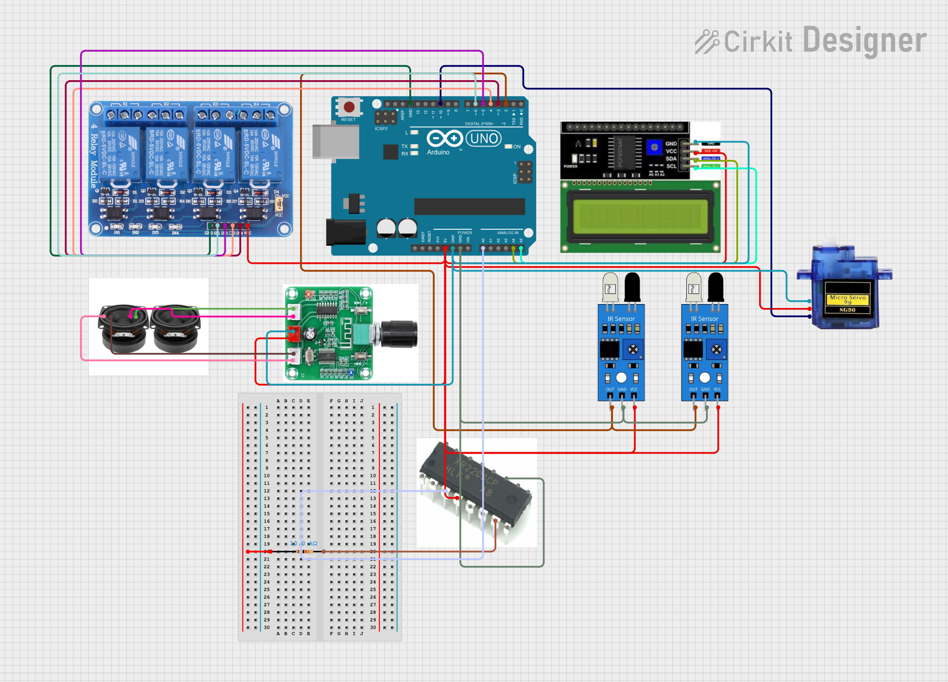
Circuit Documentation
Summary
This circuit involves an Arduino UNO microcontroller that controls a 4-channel relay module, an I2C LCD display, two IR sensors, a micro servo, a PAM8403 amplifier, an XR2206 function generator, and a speaker. The Arduino UNO is programmed to display messages on the LCD, control the relays, and generate a square wave. The IR sensors are used for input detection, and the micro servo is controlled via PWM. The PAM8403 amplifier drives the speaker.
Component List
Relay 4 Channel 5V
- Description: A relay module with 4 channels, used to control high voltage devices.
- Pins: GND, IN1, IN2, IN3, IN4, VCC, COM1, COM2, COM3, COM4, NO1, NO2, NO3, NO4, NC1, NC2, NC3, NC4
IR Sensor
- Description: Infrared sensor used for object detection.
- Pins: out, gnd, vcc
PAM8403
- Description: A small digital amplifier module.
- Pins: -, +
Arduino UNO
- Description: A microcontroller board based on the ATmega328P.
- Pins: UNUSED, IOREF, Reset, 3.3V, 5V, GND, Vin, A0, A1, A2, A3, A4, A5, SCL, SDA, AREF, D13, D12, D11, D10, D9, D8, D7, D6, D5, D4, D3, D2, D1, D0
LCD I2C Display
- Description: A 16x2 character LCD display with I2C interface.
- Pins: GND, VCC, SDA, SCL
Micro Servo 9G
- Description: A small servo motor used for precise control of angular position.
- Pins: GND, +5V, PWM
XR2206 HLF 224A8
- Description: A function generator IC.
- Pins: Pin1, Pin2, Pin3, Pin4, Pin5, Pin6, Pin7, Pin8, Pin9, Pin10, Pin11, Pin12, Pin13, Pin14, Pin15, Pin16
Speaker
- Description: A small speaker for audio output.
- Pins: +, -
Resistor
- Description: A resistor with a resistance of 10k Ohms.
- Pins: pin1, pin2
Wiring Details
Relay 4 Channel 5V
- GND connected to Arduino UNO GND
- IN1 connected to Arduino UNO D6
- IN2 connected to Arduino UNO D5
- IN3 connected to Arduino UNO D4
- IN4 connected to Arduino UNO D3
- VCC connected to XR2206 Pin4, PAM8403 +, IR Sensor vcc, Micro Servo +5V, Arduino UNO 5V, IR Sensor vcc, LCD I2C Display VCC
IR Sensor (Instance 1)
- out connected to Arduino UNO D2
- gnd connected to XR2206 Pin11, Arduino UNO GND
IR Sensor (Instance 2)
- out connected to Arduino UNO D2
- gnd connected to XR2206 Pin11, Arduino UNO GND
PAM8403
- + connected to Speaker +
- - connected to Speaker -
Arduino UNO
- GND connected to Relay 4 Channel 5V GND, PAM8403 -, Micro Servo GND, LCD I2C Display GND
- A4 connected to LCD I2C Display SDA
- A5 connected to LCD I2C Display SCL
- A0 connected to XR2206 Pin3
- D10 connected to Micro Servo PWM
LCD I2C Display
- GND connected to Arduino UNO GND
- VCC connected to Arduino UNO 5V
- SDA connected to Arduino UNO A4
- SCL connected to Arduino UNO A5
Micro Servo 9G
- GND connected to Arduino UNO GND
- +5V connected to Arduino UNO 5V
- PWM connected to Arduino UNO D10
XR2206 HLF 224A8
- Pin3 connected to Arduino UNO A0
- Pin4 connected to Relay 4 Channel 5V VCC
- Pin7 connected to Resistor pin2
- Pin11 connected to IR Sensor gnd
Speaker
- + connected to PAM8403 +
- - connected to PAM8403 -
Resistor
- pin1 connected to XR2206 Pin7
Code Documentation
/*
 * This Arduino Sketch initializes an I2C LCD display and controls a 4-channel
 * relay module. The LCD displays a welcome message and then continuously
 * updates to show the frequency of a square wave generated on one of the
 * relay control pins. The relays can be controlled via digital pins D3, D4,
 * D5, and D6.
 */

#include <Wire.h>
#include <LiquidCrystal_I2C.h>

// Initialize the LCD with I2C address 0x27 and 16x2 display
LiquidCrystal_I2C lcd(0x27, 16, 2);

// Relay control pins
const int relay1 = 6;
const int relay2 = 5;
const int relay3 = 4;
const int relay4 = 3;

// Frequency measurement variables
unsigned long previousMillis = 0;
const long interval = 1000; // Interval for frequency calculation (1 second)
int frequency = 0;

void setup() {
  // Initialize the LCD
  lcd.begin(16, 2); // Corrected to include the number of columns and rows
  lcd.backlight();
  lcd.setCursor(0, 0);
  lcd.print("Welcome!");
  lcd.setCursor(0, 1);
  lcd.print("Relay Control");
  delay(2000); // Display welcome message for 2 seconds

  // Set relay pins as outputs
  pinMode(relay1, OUTPUT);
  pinMode(relay2, OUTPUT);
  pinMode(relay3, OUTPUT);
  pinMode(relay4, OUTPUT);

  // Initialize relays to off
  digitalWrite(relay1, LOW);
  digitalWrite(relay2, LOW);
  digitalWrite(relay3, LOW);
  digitalWrite(relay4, LOW);
}

void loop() {
  unsigned long currentMillis = millis();

  // Turn on relay1
  digitalWrite(relay1, HIGH);
  delay(1000); // Wait for 1 second
  // Turn off relay1
  digitalWrite(relay1, LOW);
  delay(1000); // Wait for 1 second

  // Turn on relay2
  digitalWrite(relay2, HIGH);
  delay(1000); // Wait for 1 second
  // Turn off relay2
  digitalWrite(relay2, LOW);
  delay(1000); // Wait for 1 second

  // Turn on relay3
  digitalWrite(relay3, HIGH);
  delay(1000); // Wait for 1 second
  // Turn off relay3
  digitalWrite(relay3, LOW);
  delay(1000); // Wait for 1 second

  // Turn on relay4
  digitalWrite(relay4, HIGH);
  delay(1000); // Wait for 1 second
  // Turn off relay4
  digitalWrite(relay4, LOW);
  delay(1000); // Wait for 1 second

  // Generate square wave on relay1 pin
  digitalWrite(6, HIGH);
  delay(500); // 500ms HIGH
  digitalWrite(6, LOW);
  delay(500); // 500ms LOW

  // Calculate frequency every second
  if (currentMillis - previousMillis >= interval) {
    previousMillis = currentMillis;
    frequency = 1000; // Frequency is 1 Hz (1 cycle per second)

    // Update LCD with frequency
    lcd.clear();
    lcd.setCursor(0, 0);
    lcd.print("Frequency:");
    lcd.setCursor(0, 1);
    lcd.print(frequency);
    lcd.print(" Hz");
  }
}
This code initializes the I2C LCD display and sets up the relay control pins. It displays a welcome message on the LCD and then enters a loop where it sequentially turns on and off each relay. Additionally, it generates a square wave on one of the relay control pins and updates the LCD with the frequency of the square wave.