
Arduino UNO-Based Smart Water Flow and Temperature Control System with LCD Display
View and Edit Project In Cirkit Designer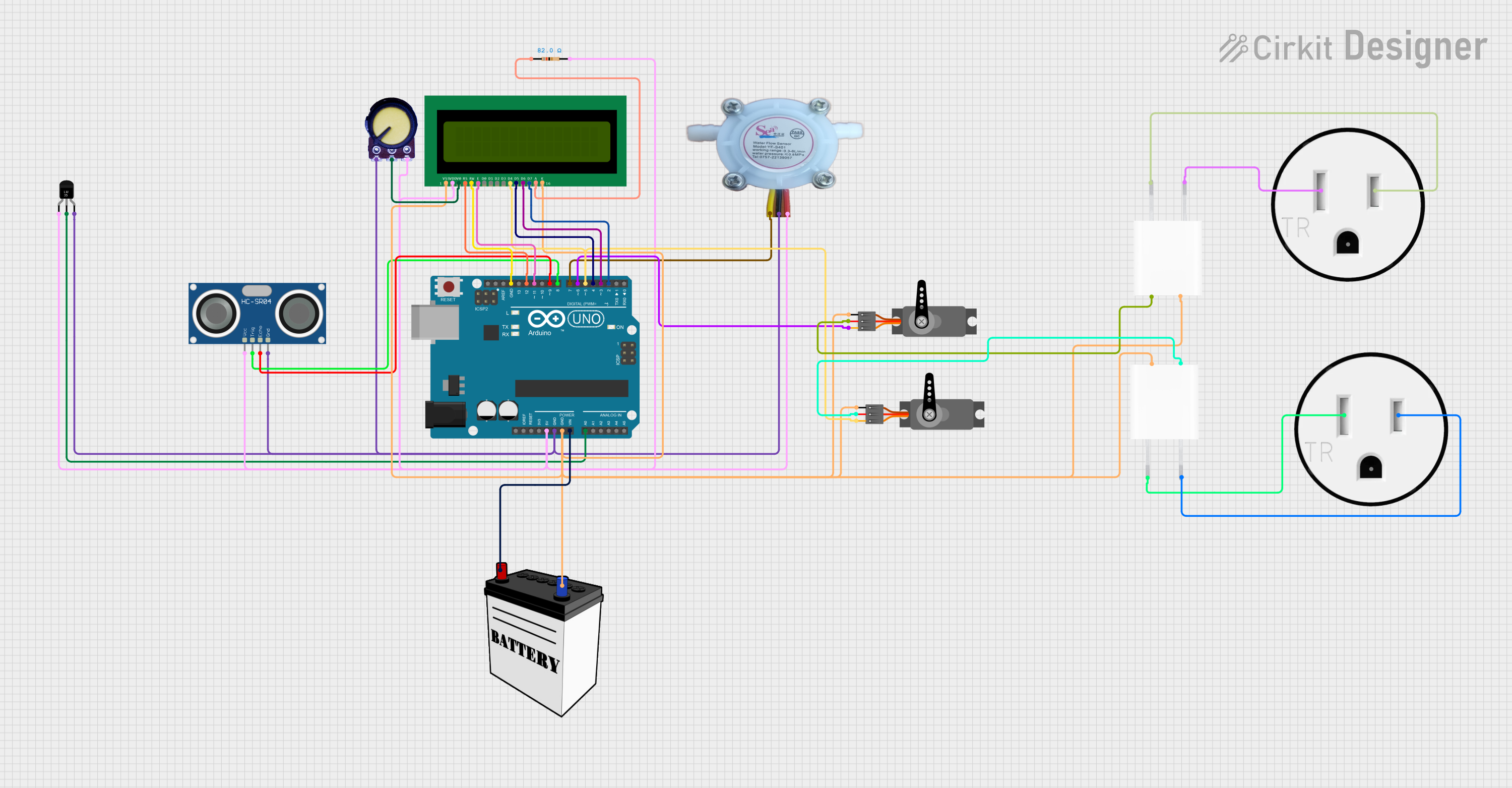
Circuit Documentation
Summary
This circuit is designed to monitor and control water flow and temperature using an Arduino UNO. It includes sensors for temperature and water flow rate, an ultrasonic sensor for distance measurement, servos for valve control, and an LCD for displaying information. The circuit is powered by a combination of a 12V battery and 5V adapters.
Component List
Arduino UNO
- Description: Microcontroller board based on the ATmega328P.
- Pins: UNUSED, IOREF, Reset, 3.3V, 5V, GND, Vin, A0, A1, A2, A3, A4, A5, SCL, SDA, AREF, D13, D12, D11, D10, D9, D8, D7, D6, D5, D4, D3, D2, D1, D0
Water Flow Rate Sensor YF-S401
- Description: Sensor to measure the flow rate of water.
- Pins: GND negative, IN positive, OUT signal output
HC-SR04 Ultrasonic Sensor
- Description: Sensor to measure distance using ultrasonic waves.
- Pins: VCC, TRIG, ECHO, GND
Servo
- Description: Actuator for controlling valves.
- Pins: GND, VCC, PWM
Temperature Sensor (LM35)
- Description: Sensor to measure temperature.
- Pins: +Vs, Vout, GND
5V Adapter
- Description: Adapter to convert AC to 5V DC.
- Pins: AC In 1, AC In 2, 5V, GND
120V Outlet
- Description: Standard electrical outlet.
- Pins: AC Neutral, AC Hot, GND
16X2 LCD
- Description: Display module to show information.
- Pins: VSS, VDD, V0, RS, RW, E, D1, D0, D2, D3, D4, D6, D5, D7, A, K
Potentiometer
- Description: Variable resistor for adjusting voltage.
- Pins: GND, Output, VCC
Resistor
- Description: 82 Ohms resistor.
- Pins: pin1, pin2
12V Battery
- Description: Battery to provide 12V power.
- Pins: VCC, GND
Wiring Details
Arduino UNO
- 5V: Connected to VDD of 16X2 LCD, VCC of Potentiometer, VCC of HC-SR04 Ultrasonic Sensor, +Vs of Temperature Sensor (LM35), pin2 of Resistor, IN positive of Water Flow Rate Sensor YF-S401
- GND: Connected to GND of Potentiometer, GND of HC-SR04 Ultrasonic Sensor, GND of Temperature Sensor (LM35), GND negative of Water Flow Rate Sensor YF-S401, VSS and K of 16X2 LCD, GND of Servo, GND of 5V Adapter, GND of 12V Battery
- Vin: Connected to VCC of 12V Battery
- A0: Connected to Vout of Temperature Sensor (LM35)
- D12: Connected to RS of 16X2 LCD
- D11: Connected to E of 16X2 LCD
- D9: Connected to ECHO of HC-SR04 Ultrasonic Sensor
- D8: Connected to TRIG of HC-SR04 Ultrasonic Sensor
- D7: Connected to OUT signal output of Water Flow Rate Sensor YF-S401
- D6: Connected to PWM of Servo
- D5: Connected to D4 of 16X2 LCD
- D4: Connected to D5 of 16X2 LCD
- D3: Connected to D6 of 16X2 LCD
- D2: Connected to D7 of 16X2 LCD
Water Flow Rate Sensor YF-S401
- GND negative: Connected to GND of Arduino UNO
- IN positive: Connected to 5V of Arduino UNO
- OUT signal output: Connected to D7 of Arduino UNO
HC-SR04 Ultrasonic Sensor
- VCC: Connected to 5V of Arduino UNO
- TRIG: Connected to D8 of Arduino UNO
- ECHO: Connected to D9 of Arduino UNO
- GND: Connected to GND of Arduino UNO
Servo
- GND: Connected to GND of Arduino UNO
- VCC: Connected to 5V of 5V Adapter
- PWM: Connected to D6 of Arduino UNO
Temperature Sensor (LM35)
- +Vs: Connected to 5V of Arduino UNO
- Vout: Connected to A0 of Arduino UNO
- GND: Connected to GND of Arduino UNO
5V Adapter
- GND: Connected to GND of Arduino UNO
- 5V: Connected to VCC of Servo
- AC In 1: Connected to AC Hot of 120V Outlet
- AC In 2: Connected to AC Neutral of 120V Outlet
120V Outlet
- AC Neutral: Connected to AC In 2 of 5V Adapter
- AC Hot: Connected to AC In 1 of 5V Adapter
- GND: Not connected
16X2 LCD
- VSS: Connected to GND of Arduino UNO
- VDD: Connected to 5V of Arduino UNO
- V0: Connected to Output of Potentiometer
- RS: Connected to D12 of Arduino UNO
- RW: Connected to GND of Arduino UNO
- E: Connected to D11 of Arduino UNO
- D4: Connected to D5 of Arduino UNO
- D5: Connected to D4 of Arduino UNO
- D6: Connected to D3 of Arduino UNO
- D7: Connected to D2 of Arduino UNO
- A: Connected to pin1 of Resistor
- K: Connected to GND of Arduino UNO
Potentiometer
- GND: Connected to GND of Arduino UNO
- Output: Connected to V0 of 16X2 LCD
- VCC: Connected to 5V of Arduino UNO
Resistor
- pin1: Connected to A of 16X2 LCD
- pin2: Connected to 5V of Arduino UNO
12V Battery
- VCC: Connected to Vin of Arduino UNO
- GND: Connected to GND of Arduino UNO
Documented Code
#include <Servo.h>
#include <LiquidCrystal.h>

// Pin definitions
const int tempPin = A0;      // Temperature sensor pin
const int flowPin = 7;       // Flow rate sensor pin
const int trigPin = 8;       // Distance sensor Trig
const int echoPin = 9;       // Distance sensor Echo
const int hotServoPin = 6;   // Servo for hot water valve
const int coldServoPin = 5;  // Servo for cold water valve

// Objects
Servo hotServo, coldServo;
LiquidCrystal lcd(12, 11, 5, 4, 3, 2);

// Variables
volatile int flowPulseCount = 0;
float flowRate = 0.0;
int currentTemp = 0;
int targetTemp = 90;    // Target temperature in Fahrenheit
int targetFlow = 13;    // Target flow in mL/sec

void setup() {
  // Initialize serial
  Serial.begin(9600);

  // LCD initialization
  lcd.begin(16, 2);
  lcd.print("Initializing...");

  // Sensor and servo initialization
  pinMode(flowPin, INPUT_PULLUP);
  attachInterrupt(digitalPinToInterrupt(flowPin), countFlowPulse, FALLING);

  pinMode(trigPin, OUTPUT);
  pinMode(echoPin, INPUT);

  hotServo.attach(hotServoPin);
  coldServo.attach(coldServoPin);

  // Default servo positions
  hotServo.write(90);  // Middle position
  coldServo.write(90);

  delay(2000);
  lcd.clear();
}

void loop() {
  // Read sensors
  currentTemp = readTemperature();
  flowRate = calculateFlowRate();

  // Display data
  lcd.setCursor(0, 0);
  lcd.print("Temp: ");
  lcd.print(currentTemp);
  lcd.print("F");

  lcd.setCursor(0, 1);
  lcd.print("Flow: ");
  lcd.print(flowRate);
  lcd.print(" mL/s");

  // Adjust temperature and flow
  adjustValves();

  delay(500);  // Delay for stability
}

// Temperature reading (mock example)
int readTemperature()