
Arduino UNO-Based Keypad-Controlled Solenoid Lock with Buzzer Feedback
View and Edit Project In Cirkit Designer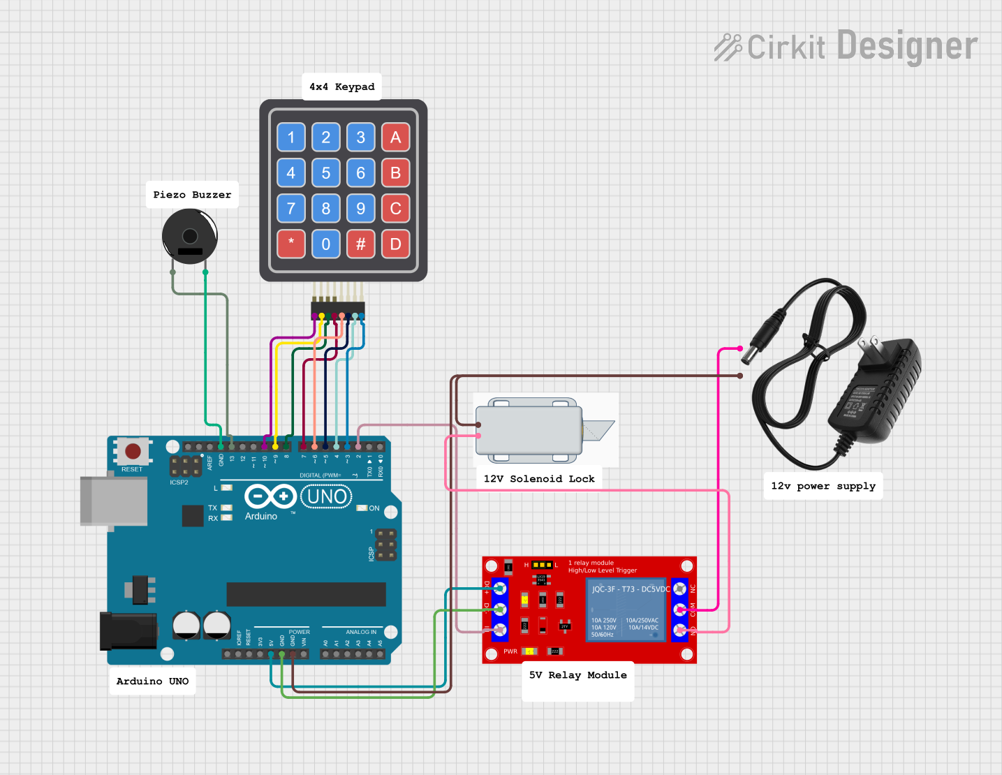
Circuit Documentation
Summary
This circuit is designed to control a 12V solenoid lock using an Arduino UNO, a 4x4 Keypad, a Piezo Buzzer, and a 1 Channel 5V Relay Module. The user can input a password via the keypad, and if the password is correct, the solenoid lock will unlock for a specified duration. The Piezo Buzzer provides audio feedback for key presses and incorrect password attempts.
Component List
Arduino UNO
- Description: A microcontroller board based on the ATmega328P.
- Pins: UNUSED, IOREF, Reset, 3.3V, 5V, GND, Vin, A0, A1, A2, A3, A4, A5, SCL, SDA, AREF, D13, D12, D11, D10, D9, D8, D7, D6, D5, D4, D3, D2, D1, D0
4x4 Keypad (Simulator)
- Description: A 4x4 matrix keypad used for user input.
- Pins: R1, C4, R2, C2, R3, R4, C1, C3
Piezo Buzzer
- Description: A buzzer used for audio feedback.
- Pins: pin 1, pin 2
12V Solenoid Lock
- Description: A solenoid lock that operates on 12V.
- Pins: -, +
12V Power Supply
- Description: A power supply providing 12V.
- Pins: +, -
1 Channel 5V Relay Module
- Description: A relay module used to control the solenoid lock.
- Pins: VCC+, VCC- (GND), IN, N.O., COM, N.C.
Wiring Details
Arduino UNO
- 5V connected to VCC+ of the 1 Channel 5V Relay Module
- GND connected to:
- VCC- (GND) of the 1 Channel 5V Relay Module
- - of the 12V Solenoid Lock
- - of the 12V Power Supply
- pin 2 of the Piezo Buzzer
- D13 connected to pin 1 of the Piezo Buzzer
- D10 connected to R1 of the 4x4 Keypad
- D9 connected to R2 of the 4x4 Keypad
- D8 connected to R3 of the 4x4 Keypad
- D7 connected to R4 of the 4x4 Keypad
- D6 connected to C1 of the 4x4 Keypad
- D5 connected to C2 of the 4x4 Keypad
- D4 connected to C3 of the 4x4 Keypad
- D3 connected to C4 of the 4x4 Keypad
- D2 connected to IN of the 1 Channel 5V Relay Module
1 Channel 5V Relay Module
- VCC+ connected to 5V of the Arduino UNO
- VCC- (GND) connected to GND of the Arduino UNO
- IN connected to D2 of the Arduino UNO
- COM connected to + of the 12V Power Supply
- N.O. connected to + of the 12V Solenoid Lock
4x4 Keypad (Simulator)
- R1 connected to D10 of the Arduino UNO
- R2 connected to D9 of the Arduino UNO
- R3 connected to D8 of the Arduino UNO
- R4 connected to D7 of the Arduino UNO
- C1 connected to D6 of the Arduino UNO
- C2 connected to D5 of the Arduino UNO
- C3 connected to D4 of the Arduino UNO
- C4 connected to D3 of the Arduino UNO
Piezo Buzzer
- pin 1 connected to D13 of the Arduino UNO
- pin 2 connected to GND of the Arduino UNO
12V Solenoid Lock
- - connected to GND of the Arduino UNO
- + connected to N.O. of the 1 Channel 5V Relay Module
12V Power Supply
- - connected to GND of the Arduino UNO
- + connected to COM of the 1 Channel 5V Relay Module
Documented Code
#include <Keypad.h>

const byte numRows = 4; // number of rows on the keypad
const byte numCols = 4; // number of columns on the keypad

// Keymap defines the key pressed according to the row and columns as appears on the keypad
char keymap[numRows][numCols] =
{
  {'1', '2', '3', 'A'},
  {'4', '5', '6', 'B'},
  {'7', '8', '9', 'C'},
  {'*', '0', '#', 'D'}
};

// Code that shows the keypad connections to the Arduino terminals
byte rowPins[numRows] = {10, 9, 8, 7}; // Rows 0 to 3
byte colPins[numCols] = {6, 5, 4, 3}; // Columns 0 to 3

// Initializes an instance of the Keypad class
Keypad myKeypad = Keypad(makeKeymap(keymap), rowPins, colPins, numRows, numCols);

String password = "0911"; // Example password (you can change it)

const int buzzerPin = 13;
const int relayPin = 2;

unsigned long lastButtonPress = 0; // Timestamp for last button press
const unsigned long debounceDelay = 50; // Debounce delay in milliseconds

void setup()
{
  pinMode(buzzerPin, OUTPUT);
  pinMode(relayPin, OUTPUT);
  Serial.begin(9600);

  // Set the initial state of the relay (locked)
  digitalWrite(relayPin, HIGH); // Set relay to "locked" state initially
  Serial.println("Set your 4-digit password (it can include letters A-D):");
}

void loop()
{
  // Handle password entry
  String enteredPassword = "";
  int passTries = 0;

  // Loop for entering password with max 3 attempts
  while (passTries < 3) {
    enteredPassword = "";

    // Capture the password input
    while (enteredPassword.length() < 4) {
      char keypressed = myKeypad.getKey();
      if (keypressed != NO_KEY) {
        Serial.print("Key Pressed: ");
        Serial.println(keypressed);  // Print key pressed to serial monitor
        tone(buzzerPin, 1500, 100); // Short beep for key press
        enteredPassword += keypressed;
      }
    }

    Serial.println();

    // Check if the entered password is correct
    if (enteredPassword == password) {
      Serial.println("Correct Password");
      openSolenoid(); // Trigger solenoid to open for 5 seconds
      return; // Exit the loop once the password is correct
    } else {
      passTries++;
      Serial.println("Incorrect Password. Try again.");
      tone(buzzerPin, 1000, 500); // Long beep for incorrect password
    }
  }

  // If there are 3 incorrect attempts, sound the buzzer for 10 seconds
  if (passTries >= 3) {
    tone(buzzerPin, 800, 10000); // Buzzer sound for 10 seconds
    delay(10000);
    noTone(buzzerPin); // Stop buzzer sound
    Serial.println("Too many incorrect attempts. Locking system.");
  }

  // After a password attempt, the system will continue asking for the password
  Serial.println("Try entering the password again.");
}

// Function to trigger solenoid and open for 5 seconds
void openSolenoid() {
  digitalWrite(relayPin, LOW); // Unlock solenoid (set relay to LOW)
  Serial.println("Solenoid Opened");
  delay(5000); // Solenoid stays open for 5 seconds
  digitalWrite(relayPin, HIGH); // Lock solenoid (set relay to HIGH)
  Serial.println("Solenoid Locked");
}
This code initializes the keypad, sets up the pins for the buzzer and relay, and handles password entry. If the correct password is entered, the solenoid lock is unlocked for 5 seconds. If the password is incorrect, the user is given three attempts before the system locks and sounds the buzzer for 10 seconds.