
Arduino Nano Controlled Optical Encoder with I2C LCD Display
View and Edit Project In Cirkit Designer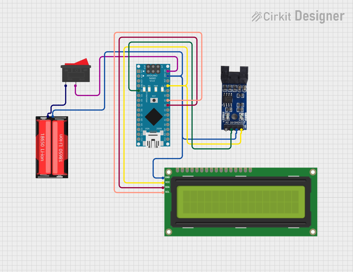
Circuit Documentation
Summary
The circuit in question is designed to interface an optical encoder sensor module with an Arduino Nano microcontroller, which also connects to an I2C LCD 16x2 screen for display purposes. Power is supplied by a 18650 Li-Ion battery, which is controlled by a rocker switch. The Arduino Nano serves as the central processing unit, reading inputs from the optical encoder and outputting data to the LCD screen.
Component List
Optical Encoder Sensor Module
- Pins: A0, D0, GND, VCC
- Description: This module is used to detect rotational position changes, which it communicates to the Arduino Nano.
Arduino Nano
- Pins: D1/TX, D0/RX, RESET, GND, D2, D3, D4, D5, D6, D7, D8, D9, D10, D11/MOSI, D12/MISO, VIN, 5V, A7, A6, A5, A4, A3, A2, A1, A0, AREF, 3V3, D13/SCK
- Description: A compact microcontroller that serves as the brain of the circuit, processing inputs and controlling outputs.
I2C LCD 16x2 Screen
- Pins: SCL, SDA, VCC (5V), GND, VDD, VO, RS, RW, E, D0, D1, D2, D3, D4, D5, D6, D7, BLA, BLK
- Description: A display module used to show information processed by the Arduino Nano.
18650 Li-Ion Battery
- Pins: Positive, Negative
- Description: Provides power to the circuit.
Rocker Switch
- Pins: 1, 2
- Description: Controls the power supply from the battery to the circuit.
Wiring Details
Optical Encoder Sensor Module
- D0 connected to Arduino Nano D2
- GND connected to common ground
- VCC connected to Arduino Nano 5V
Arduino Nano
- D2 connected to Optical Encoder Sensor Module D0
- GND connected to common ground
- 5V connected to Optical Encoder Sensor Module VCC and I2C LCD 16x2 Screen VCC (5V)
- VIN connected to Rocker Switch pin 2
- A5 connected to I2C LCD 16x2 Screen SCL
- A4 connected to I2C LCD 16x2 Screen SDA
I2C LCD 16x2 Screen
- SCL connected to Arduino Nano A5
- SDA connected to Arduino Nano A4
- VCC (5V) connected to Arduino Nano 5V
- GND connected to common ground
18650 Li-Ion Battery
- Negative connected to common ground
- Positive connected to Rocker Switch pin 1
Rocker Switch
- Pin 1 connected to 18650 Li-Ion Battery Positive
- Pin 2 connected to Arduino Nano VIN
Documented Code
Arduino Nano Code (sketch.ino)
void setup() {
  // put your setup code here, to run once:

}

void loop() {
  // put your main code here, to run repeatedly:

}
Note: The provided code is a template and does not contain any functional code specific to the circuit's operation. It will need to be populated with the necessary setup and loop routines to handle the optical encoder input and LCD output.