
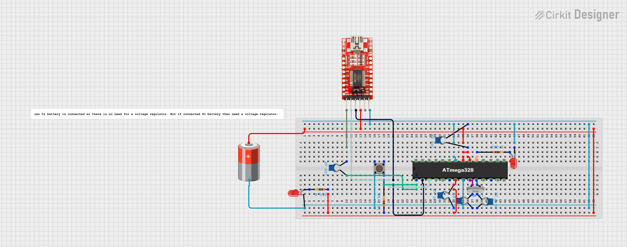
Circuit Documentation
Summary
This circuit is built around an ATMEGA328 microcontroller and includes various components such as resistors, capacitors, LEDs, a crystal oscillator, a pushbutton, a 5V battery, and an FTDI programmer. The circuit is designed to blink an LED connected to pin D13 of the ATMEGA328 microcontroller.
Component List
ATMEGA328 Microcontroller
- Pins: RESET, D0, D1, D2, D3, D4, VCC, GND, CRYSTAL, D5, D6, D7, D8, D9, D10, D11, D12, D13, AREF, A0, A1, A2, A3, A4, A5
- Description: Main microcontroller used for processing and control.
5V Battery
- Pins: +, -
- Description: Power supply for the circuit.
Resistor (10k Ohms)
- Pins: pin1, pin2
- Description: Used for pull-up or current limiting purposes.
- Properties: Resistance: 10k Ohms
Resistor (200 Ohms)
- Pins: pin1, pin2
- Description: Used for current limiting.
- Properties: Resistance: 200 Ohms
Ceramic Capacitor (0.1 µF)
- Pins: pin0, pin1
- Description: Used for decoupling and filtering.
- Properties: Capacitance: 0.1 µF
Ceramic Capacitor (22 pF)
- Pins: pin0, pin1
- Description: Used for crystal oscillator stabilization.
- Properties: Capacitance: 22 pF
Crystal Oscillator
- Pins: pin 0, pin 1
- Description: Provides clock signal for the microcontroller.
LED: Two Pin (red)
- Pins: cathode, anode
- Description: Indicator LED.
FTDI Programmer
- Pins: DTR, RX, TX, VCC, CTS, GND
- Description: Used for programming the microcontroller.
Pushbutton
- Pins: Pin 3 (out), Pin 4 (out), Pin 1 (in), Pin 2 (in)
- Description: Used for user input.
Wiring Details
ATMEGA328 Microcontroller
VCC is connected to:
- Resistor (10k Ohms) pin1
- Ceramic Capacitor (0.1 µF) pin0
- 5V Battery +
- FTDI Programmer VCC
GND is connected to:
- Pushbutton Pin 2 (in)
- Ceramic Capacitor (0.1 µF) pin1
- 5V Battery -
- FTDI Programmer GND
- LED (red) cathode
RESET is connected to:
- Resistor (10k Ohms) pin2
- Pushbutton Pin 4 (out)
- Ceramic Capacitor (0.1 µF) pin0
D0 is connected to FTDI Programmer TX
D1 is connected to FTDI Programmer RX
D13 is connected to Resistor (200 Ohms) pin1
CRYSTAL is connected to:
- Crystal Oscillator pin 0
- Crystal Oscillator pin 1
- Ceramic Capacitor (22 pF) pin0
- Ceramic Capacitor (22 pF) pin1
AREF is connected to 5V Battery +
5V Battery
+ is connected to:
- ATMEGA328 VCC
- FTDI Programmer VCC
- Resistor (10k Ohms) pin1
- Ceramic Capacitor (0.1 µF) pin0
- is connected to:
- ATMEGA328 GND
- FTDI Programmer GND
- Pushbutton Pin 2 (in)
- Ceramic Capacitor (0.1 µF) pin1
- LED (red) cathode
Resistor (10k Ohms)
pin1 is connected to:
- ATMEGA328 VCC
- 5V Battery +
- Ceramic Capacitor (0.1 µF) pin0
pin2 is connected to:
- ATMEGA328 RESET
- Pushbutton Pin 4 (out)
- Ceramic Capacitor (0.1 µF) pin0
Resistor (200 Ohms)
pin1 is connected to ATMEGA328 D13
pin2 is connected to LED (red) anode
Ceramic Capacitor (0.1 µF)
pin0 is connected to:
- ATMEGA328 VCC
- Resistor (10k Ohms) pin1
- 5V Battery +
pin1 is connected to:
- ATMEGA328 GND
- 5V Battery -
Ceramic Capacitor (22 pF)
pin0 is connected to:
- Crystal Oscillator pin 0
- ATMEGA328 CRYSTAL
pin1 is connected to:
- Crystal Oscillator pin 1
- ATMEGA328 CRYSTAL
Crystal Oscillator
pin 0 is connected to:
- Ceramic Capacitor (22 pF) pin0
- ATMEGA328 CRYSTAL
pin 1 is connected to:
- Ceramic Capacitor (22 pF) pin1
- ATMEGA328 CRYSTAL
LED: Two Pin (red)
cathode is connected to:
- ATMEGA328 GND
- 5V Battery -
- FTDI Programmer GND
anode is connected to:
- Resistor (200 Ohms) pin2
FTDI Programmer
VCC is connected to:
- ATMEGA328 VCC
- 5V Battery +
GND is connected to:
- ATMEGA328 GND
- 5V Battery -
- LED (red) cathode
DTR is connected to Ceramic Capacitor (0.1 µF) pin1
RX is connected to ATMEGA328 D1
TX is connected to ATMEGA328 D0
Pushbutton
Pin 2 (in) is connected to:
- ATMEGA328 GND
- 5V Battery -
Pin 4 (out) is connected to:
- Resistor (10k Ohms) pin2
- ATMEGA328 RESET
- Ceramic Capacitor (0.1 µF) pin0
Code Documentation
ATMEGA328 Microcontroller Code
int LEDpin = D13;
int delayT = 1000;

void setup() {
  // put your setup code here, to run once:
  pinMode(LEDpin, OUTPUT);
}

void loop() {
  // put your main code here, to run repeatedly:
  digitalWrite(LEDpin, HIGH);
  delay(delayT);
  digitalWrite(LEDpin, LOW);
  delay(delayT);
}
Description:
- LEDpin: Defines the pin connected to the LED.
- delayT: Defines the delay time in milliseconds.
- setup(): Configures the LED pin as an output.
- loop(): Turns the LED on and off with a delay, creating a blinking effect.