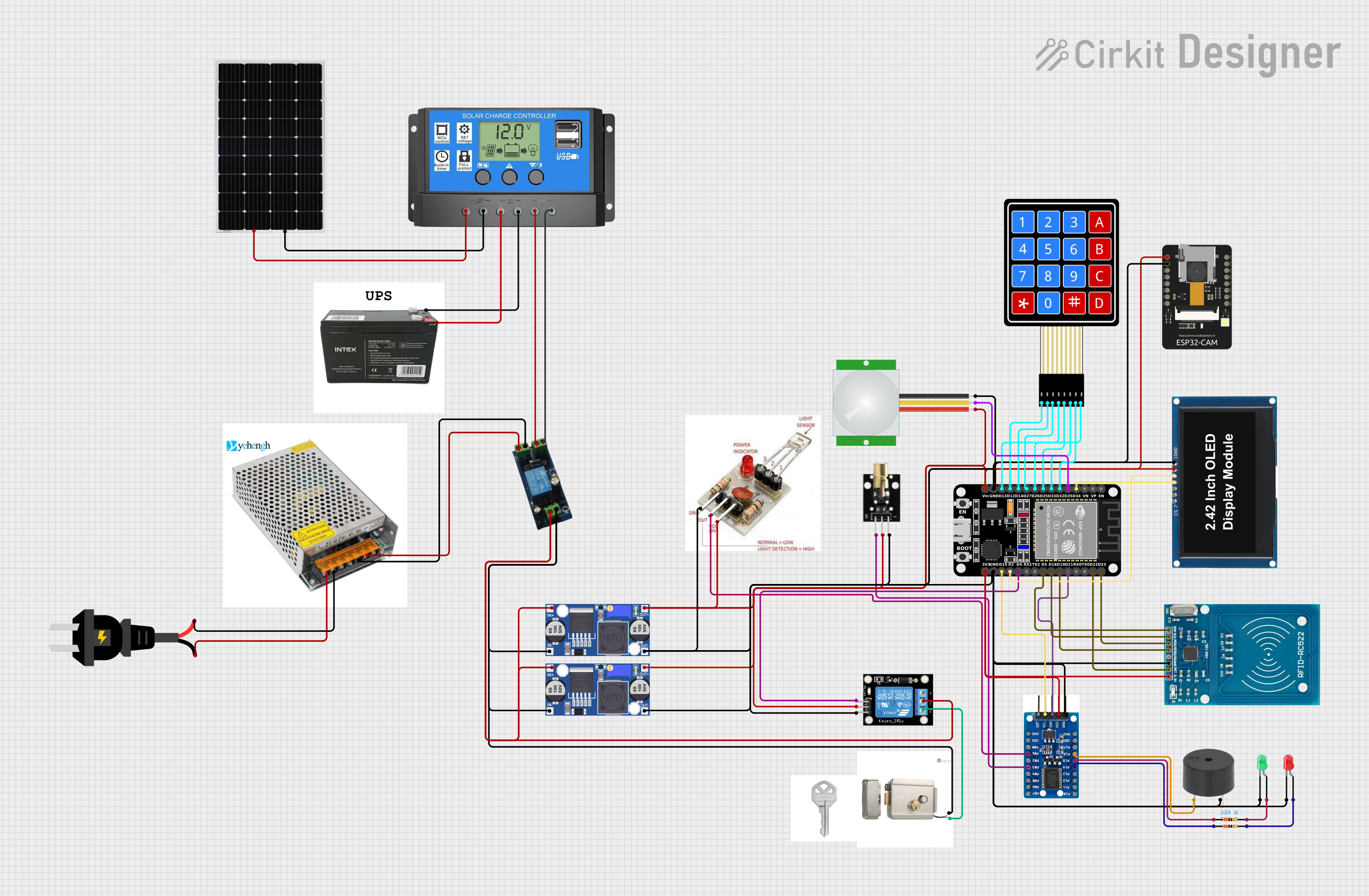
Solar-Powered ESP32 Access Control System with RFID and PIR Sensor

Circuit Documentation
Summary
This circuit integrates various components including sensors, a microcontroller, input/output devices, and power management modules to create a complex system. The central processing unit is an ESP32 microcontroller, which interfaces with a PIR sensor, a laser emitter and receiver, a keypad, an IO expander, an RFID module, a buzzer, LEDs, and a relay module. The circuit is powered by a combination of a solar panel, a charge controller, a UPS battery, and a centralized power supply, with buck converters to regulate voltage levels. The system likely serves a security or access control purpose, given the presence of the PIR sensor, RFID reader, and electric lock.
Component List
Sensors
- KY-008 Laser Emitter: Emits a laser beam for detection purposes.
- PIR Sensor: Detects motion through changes in infrared levels.
- Laser Receiver Module: Receives the laser signal from the emitter.
Microcontroller
- ESP32 (30 pin): A powerful microcontroller with Wi-Fi capabilities.
Input Devices
- 4X4 Membrane Matrix Keypad: Allows user input through a 4x4 matrix of keys.
Expanders and Modules
- PCF8575 IO Expander: Expands the number of IO pins available to the microcontroller.
- RFID-RC522: An RFID reader for contactless communication and identification.
- KY-019 Relay Module 1 Channel: Controls high power devices with a low power signal.
Output Devices
- Buzzer: Emits an audible alert.
- LED: Two Pin (green): A green indicator light.
- LED: Two Pin (red): A red indicator light.
- OLED Display 2.42": A small screen for displaying data.
Power Management
- Solar Panel: Converts sunlight into electrical energy.
- AC Source: Provides alternating current power.
- Solar Charge Controller: Manages the power from the solar panel to charge the battery and power the load.
- UPS BATTERY: Provides backup power in case of power failure.
- Buck Converter: Steps down voltage to a lower level.
- Centralized Power Supply: Distributes power to various components in the circuit.
Actuators
- Electric Lock: An electronically controlled lock mechanism.
Miscellaneous
- Comment: A placeholder for additional notes or comments.
- Custom 1: A custom component with unspecified functionality.
- Key: A component representing a physical key or switch.
Wiring Details
KY-008 Laser Emitter
- SIG: Connected to PCF8575 IO Expander P03.
- 5V: Connected to Buck Converter OUT+.
- GND: Connected to Buck Converter OUT-.
PIR Sensor
- VDD: Connected to Buck Converter OUT+.
- SIG: Connected to ESP32 D35.
- GND: Connected to Buck Converter OUT-.
Laser Receiver Module
- VCC: Connected to Buck Converter OUT+.
- OUTPUT: Connected to PCF8575 IO Expander P01.
- GROUND: Connected to Buck Converter OUT-.
ESP32 (30 pin)
- Various Pins: Connected to the 4X4 Membrane Matrix Keypad, OLED Display, RFID-RC522, PCF8575 IO Expander, KY-019 Relay Module, and other components as per the net list.
4X4 Membrane Matrix Keypad
- R1, R2, R3, R4, C1, C2, C3, C4: Each connected to corresponding pins on the ESP32.
PCF8575 IO Expander
- P00 - P17: Various connections to the ESP32, KY-008 Laser Emitter, Laser Receiver Module, Buzzer, Resistors, and LEDs.
- INT: Not connected.
- SCL, SDA: Connected to ESP32 D21 and D15 for I2C communication.
- VDD: Connected to ESP32 3V3.
- GND: Connected to Buck Converter OUT-.
RFID-RC522
- VCC (3.3V): Connected to ESP32 3V3.
- RST, IRQ, MISO, MOSI, SCK, SDA: Connected to corresponding pins on the ESP32.
- GND: Connected to Buck Converter OUT-.
Buzzer
- PIN: Connected to PCF8575 IO Expander P16.
- GND: Connected to Buck Converter OUT-.
LEDs (Green and Red)
- Cathode: Connected to Buck Converter OUT-.
- Anode: Connected to respective resistors, which are then connected to PCF8575 IO Expander P14 and P15.
KY-019 Relay Module 1 Channel
- S: Connected to ESP32 D4.
- 5V: Connected to Buck Converter OUT+.
- GND: Connected to Buck Converter OUT-.
- NC, COM, NO: Used for switching, with COM connected to Buck Converter IN+ and NO connected to Electric Lock VCC.
Solar Panel
- +: Connected to Solar Charge Controller Solar Cell +.
- -: Connected to Solar Charge Controller Solar Cell -.
AC Source
- +: Connected to Centralized Power Supply L.
- -: Connected to Centralized Power Supply N.
Solar Charge Controller
- Solar Cell +, Solar Cell -: Connected to Solar Panel.
- Battery +, Battery -: Connected to UPS BATTERY.
- Load +, Load -: Connected to Custom 1 vcc and gnd.
UPS BATTERY
- VCC: Connected to Solar Charge Controller Battery +.
- GND: Connected to Solar Charge Controller Battery -.
Buck Converter
- IN+, IN-: Connected to Custom 1 vcc and gnd, and to Centralized Power Supply dc + and dc -.
- OUT+, OUT-: Connected to various components for power distribution.
OLED Display 2.42"
- GND, VCC, SCK, SDA, RES, DC, CS: Connected to corresponding pins on the ESP32.
Electric Lock
- VCC: Connected to KY-019 Relay Module NO.
- GND: Connected to Buck Converter IN-.
Centralized Power Supply
- L, N, com, DC -, dc -, dc +: Connected to AC Source and Custom 1.
Documented Code
No code was provided for the microcontrollers in the circuit. Therefore, this section is left blank until the relevant code is available for documentation.