
Arduino UNO and L298N Motor Driver Controlled Robot with PS2 Controller and Battery Power
View and Edit Project In Cirkit Designer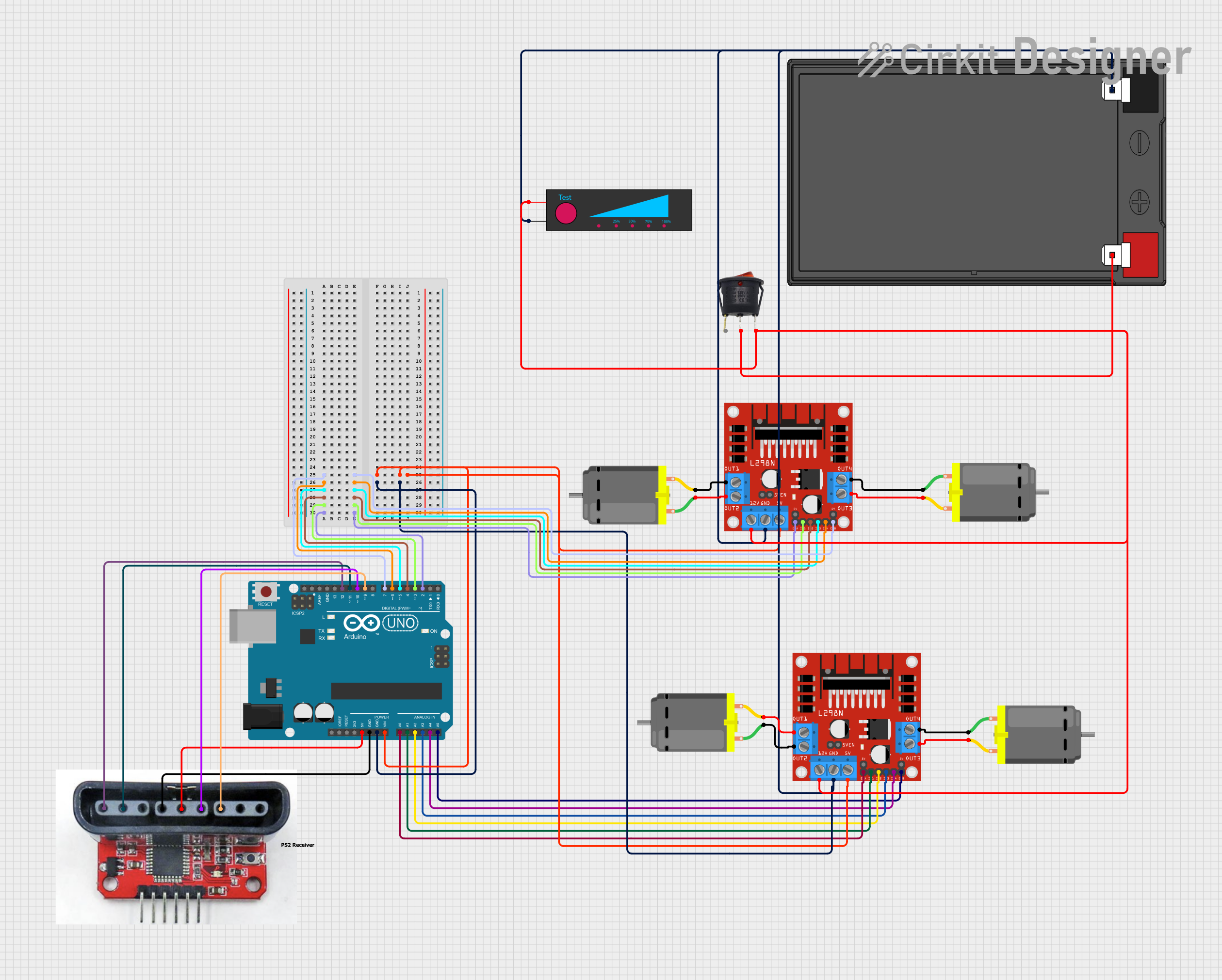
Circuit Documentation
Summary
This circuit involves an Arduino UNO microcontroller, two L298N DC motor drivers, a 12V 7Ah battery, a round rocker switch, a battery level indicator, multiple DC motors, and a PS2 controller receiver. The Arduino UNO is used to control the motor drivers, which in turn control the DC motors. The PS2 controller receiver is used for user input, and the battery level indicator monitors the battery status.
Component List
Arduino UNO
- Description: A microcontroller board based on the ATmega328P.
- Pins: UNUSED, IOREF, Reset, 3.3V, 5V, GND, Vin, A0, A1, A2, A3, A4, A5, SCL, SDA, AREF, D13, D12, D11, D10, D9, D8, D7, D6, D5, D4, D3, D2, D1, D0
L298N DC Motor Driver
- Description: A dual H-Bridge motor driver module.
- Pins: OUT1, OUT2, 12V, GND, 5V, OUT3, OUT4, 5V-ENA-JMP-I, 5V-ENA-JMP-O, +5V-J1, +5V-J2, ENA, IN1, IN2, IN3, IN4, ENB
12V 7Ah Battery
- Description: A rechargeable lead-acid battery.
- Pins: 12v +, 12v -
Round Rocker Switch
- Description: A switch to control the power supply.
- Pins: Input +, Ground, Output +
Battery Level Indicator
- Description: A device to monitor the battery voltage.
- Pins: +, -
DC Motor
- Description: A simple DC motor.
- Pins: pin 1, pin 2
PS2 Controller Receiver
- Description: A receiver for PS2 controller signals.
- Pins: Data, CMD, Ground, 3.3V-5V, Attention, Clock
Wiring Details
Arduino UNO
- D7: Connected to ENB of L298N DC motor driver
- Vin: Connected to 5V of both L298N DC motor drivers
- GND: Connected to GND of both L298N DC motor drivers, Battery Level Indicator, and 12V 7Ah Battery
- D6: Connected to IN4 of L298N DC motor driver
- D5: Connected to IN3 of L298N DC motor driver
- D4: Connected to IN2 of L298N DC motor driver
- D3: Connected to IN1 of L298N DC motor driver
- D2: Connected to ENA of L298N DC motor driver
- 5V: Connected to 3.3V-5V of PS2 controller receiver
- A0: Connected to ENA of L298N DC motor driver
- A1: Connected to IN1 of L298N DC motor driver
- A2: Connected to IN2 of L298N DC motor driver
- A3: Connected to IN3 of L298N DC motor driver
- A4: Connected to IN4 of L298N DC motor driver
- A5: Connected to ENB of L298N DC motor driver
- D12: Connected to Data of PS2 controller receiver
- D11: Connected to CMD of PS2 controller receiver
- D10: Connected to Attention of PS2 controller receiver
- D9: Connected to Clock of PS2 controller receiver
L298N DC Motor Driver (1)
- ENB: Connected to D7 of Arduino UNO
- 5V: Connected to 5V of L298N DC motor driver (2) and Vin of Arduino UNO
- IN4: Connected to D6 of Arduino UNO
- GND: Connected to GND of Battery Level Indicator, L298N DC motor driver (2), 12V 7Ah Battery, and Arduino UNO
- IN3: Connected to D5 of Arduino UNO
- IN2: Connected to D4 of Arduino UNO
- IN1: Connected to D3 of Arduino UNO
- ENA: Connected to D2 of Arduino UNO
- OUT1: Connected to pin 2 of DC Motor (1)
- OUT2: Connected to pin 1 of DC Motor (1)
- 12V: Connected to + of Battery Level Indicator, Output + of Round Rocker Switch, and 12V of L298N DC motor driver (2)
- OUT3: Connected to pin 2 of DC Motor (2)
- OUT4: Connected to pin 1 of DC Motor (2)
L298N DC Motor Driver (2)
- 5V: Connected to 5V of L298N DC motor driver (1) and Vin of Arduino UNO
- GND: Connected to GND of Battery Level Indicator, L298N DC motor driver (1), 12V 7Ah Battery, and Arduino UNO
- ENA: Connected to A0 of Arduino UNO
- IN1: Connected to A1 of Arduino UNO
- IN2: Connected to A2 of Arduino UNO
- IN3: Connected to A3 of Arduino UNO
- IN4: Connected to A4 of Arduino UNO
- ENB: Connected to A5 of Arduino UNO
- OUT1: Connected to pin 2 of DC Motor (3)
- OUT2: Connected to pin 1 of DC Motor (3)
- OUT3: Connected to pin 2 of DC Motor (4)
- OUT4: Connected to pin 1 of DC Motor (4)
- 12V: Connected to + of Battery Level Indicator, Output + of Round Rocker Switch, and 12V of L298N DC motor driver (1)
12V 7Ah Battery
- 12v +: Connected to Input + of Round Rocker Switch
- 12v -: Connected to GND of Battery Level Indicator, L298N DC motor driver (1), L298N DC motor driver (2), and Arduino UNO
Round Rocker Switch
- Input +: Connected to 12v + of 12V 7Ah Battery
- Output +: Connected to 12V of L298N DC motor driver (1) and L298N DC motor driver (2)
Battery Level Indicator
- +: Connected to 12V of L298N DC motor driver (1) and L298N DC motor driver (2)
- -: Connected to GND of L298N DC motor driver (1), L298N DC motor driver (2), 12V 7Ah Battery, and Arduino UNO
DC Motor (1)
- pin 1: Connected to OUT2 of L298N DC motor driver (1)
- pin 2: Connected to OUT1 of L298N DC motor driver (1)
DC Motor (2)
- pin 1: Connected to OUT4 of L298N DC motor driver (1)
- pin 2: Connected to OUT3 of L298N DC motor driver (1)
DC Motor (3)
- pin 1: Connected to OUT2 of L298N DC motor driver (2)
- pin 2: Connected to OUT1 of L298N DC motor driver (2)
DC Motor (4)
- pin 1: Connected to OUT4 of L298N DC motor driver (2)
- pin 2: Connected to OUT3 of L298N DC motor driver (2)
PS2 Controller Receiver
- 3.3V-5V: Connected to 5V of Arduino UNO
- Ground: Connected to GND of Arduino UNO
- Data: Connected to D12 of Arduino UNO
- CMD: Connected to D11 of Arduino UNO
- Attention: Connected to D10 of Arduino UNO
- Clock: Connected to D9 of Arduino UNO
Documented Code
Arduino UNO Code (sketch.ino)
void setup() {
  // put your setup code here, to run once:

}

void loop() {
  // put your main code here, to run repeatedly:

}
Documentation (documentation.txt)