
Arduino Nano Controlled Bipolar Stepper Motor with LED Indicators
View and Edit Project In Cirkit Designer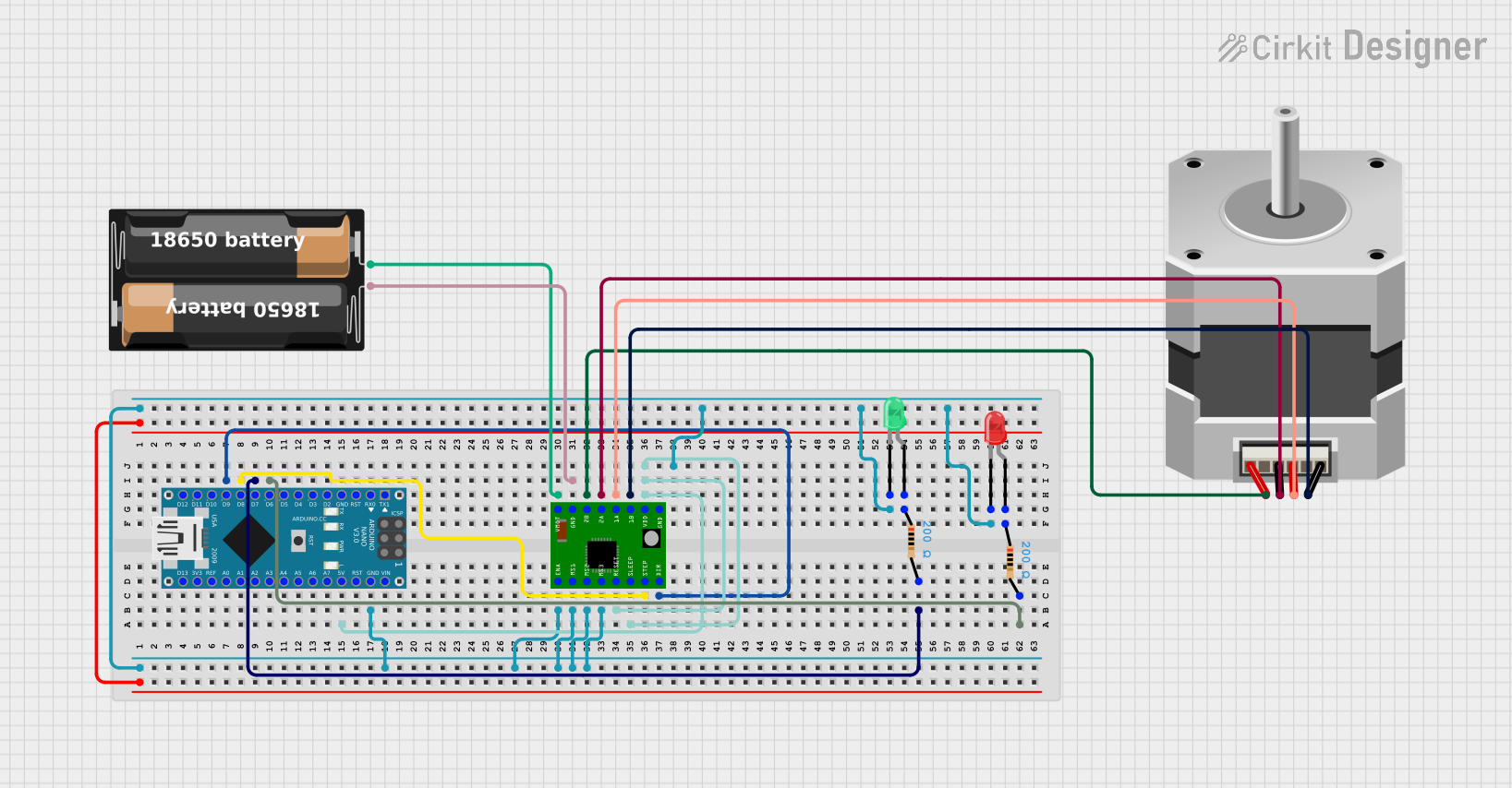
Circuit Documentation
Summary
This circuit is designed to control a bipolar stepper motor using an Arduino Nano and an A4988 stepper motor driver. The circuit also includes two LEDs (red and green) to indicate the direction of the motor's rotation. The Arduino Nano is programmed to rotate the motor clockwise and counterclockwise with pauses in between.
Component List
Stepper Motor (Bipolar)
- Pins: D, B, C, A
- Description: A bipolar stepper motor used for precise control of rotational position.
Battery Case
- Pins: +, -
- Description: Provides power to the circuit.
Arduino Nano
- Pins: D1/TX, D0/RX, RESET, GND, D2, D3, D4, D5, D6, D7, D8, D9, D10, D11/MOSI, D12/MISO, VIN, 5V, A7, A6, A5, A4, A3, A2, A1, A0, AREF, 3V3, D13/SCK
- Description: A microcontroller used to control the stepper motor and LEDs.
LED: Two Pin (red)
- Pins: cathode, anode
- Description: A red LED used to indicate the motor's counterclockwise rotation.
LED: Two Pin (green)
- Pins: cathode, anode
- Description: A green LED used to indicate the motor's clockwise rotation.
Resistor (200 Ohms)
- Pins: pin1, pin2
- Description: Used to limit the current through the LEDs.
A4988 Stepper Motor Driver Carrier
- Pins: ENABLE, MS1, MS2, MS3, RESET, SLEEP, STEP, DIR, GND, VCC, 1B, 1A, 2A, 2B, VMOT
- Description: A driver module used to control the stepper motor.
Wiring Details
Stepper Motor (Bipolar)
- Pin D connected to A4988 Stepper Motor Driver Carrier pin 1B
- Pin B connected to A4988 Stepper Motor Driver Carrier pin 1A
- Pin C connected to A4988 Stepper Motor Driver Carrier pin 2A
- Pin A connected to A4988 Stepper Motor Driver Carrier pin 2B
Battery Case
- Pin + connected to A4988 Stepper Motor Driver Carrier pin VMOT
- Pin - connected to A4988 Stepper Motor Driver Carrier pin GND
Arduino Nano
- Pin D9 connected to A4988 Stepper Motor Driver Carrier pin DIR
- Pin D8 connected to A4988 Stepper Motor Driver Carrier pin STEP
- Pin D7 connected to Resistor pin pin2
- Pin D6 connected to Resistor pin pin2
- Pin 5V connected to A4988 Stepper Motor Driver Carrier pins RESET, SLEEP, and VCC
- Pin GND connected to A4988 Stepper Motor Driver Carrier pins ENABLE, MS1, MS2, MS3, LED: Two Pin (green) pin cathode, and LED: Two Pin (red) pin cathode
LED: Two Pin (red)
- Pin anode connected to Resistor pin pin1
LED: Two Pin (green)
- Pin anode connected to Resistor pin pin1
Resistor (200 Ohms)
- Pin pin1 connected to LED: Two Pin (red) pin anode
- Pin pin2 connected to Arduino Nano pin D7
Resistor (200 Ohms)
- Pin pin1 connected to LED: Two Pin (green) pin anode
- Pin pin2 connected to Arduino Nano pin D6
A4988 Stepper Motor Driver Carrier
- Pin DIR connected to Arduino Nano pin D9
- Pin STEP connected to Arduino Nano pin D8
- Pin RESET connected to Arduino Nano pin 5V
- Pin SLEEP connected to Arduino Nano pin 5V
- Pin VCC connected to Arduino Nano pin 5V
- Pin ENABLE connected to Arduino Nano pin GND
- Pin MS1 connected to Arduino Nano pin GND
- Pin MS2 connected to Arduino Nano pin GND
- Pin MS3 connected to Arduino Nano pin GND
- Pin VMOT connected to Battery Case pin +
- Pin GND connected to Battery Case pin -
- Pin 1B connected to Stepper Motor (Bipolar) pin D
- Pin 1A connected to Stepper Motor (Bipolar) pin B
- Pin 2A connected to Stepper Motor (Bipolar) pin C
- Pin 2B connected to Stepper Motor (Bipolar) pin A
Code Documentation
// Pin definitions
#define STEP_PIN 8      // STEP pin connected to A4988
#define DIR_PIN 9       // DIR pin connected to A4988
#define GREEN_LED 6     // Green LED pin (Clockwise Indicator)
#define YELLOW_LED 7    // Yellow LED pin (Counterclockwise Indicator)

// Function prototypes
void rotateMotor(int duration, int stepDelay);

void setup() {
  // Configure motor pins
  pinMode(STEP_PIN, OUTPUT);
  pinMode(DIR_PIN, OUTPUT);

  // Configure LED pins
  pinMode(GREEN_LED, OUTPUT);
  pinMode(YELLOW_LED, OUTPUT);

  // Start with LEDs off
  digitalWrite(GREEN_LED, LOW);
  digitalWrite(YELLOW_LED, LOW);
}

void loop() {
  // Step 1: Rotate clockwise for 3 seconds
  digitalWrite(DIR_PIN, HIGH);      // Set motor direction to clockwise
  digitalWrite(GREEN_LED, HIGH);    // Turn on green LED
  rotateMotor(3000, 1000);          // Rotate for 3 seconds (step delay 1000µs)
  digitalWrite(GREEN_LED, LOW);     // Turn off green LED

  // Step 2: Stop for 5 seconds
  delay(5000);

  // Step 3: Rotate counterclockwise for 3 seconds
  digitalWrite(DIR_PIN, LOW);       // Set motor direction to counterclockwise
  digitalWrite(YELLOW_LED, HIGH);   // Turn on yellow LED
  rotateMotor(3000, 1000);          // Rotate for 3 seconds (step delay 1000µs)
  digitalWrite(YELLOW_LED, LOW);    // Turn off yellow LED

  // Step 4: Stop for 5 seconds
  delay(5000);
}

// Function to rotate the motor for a specified duration
void rotateMotor(int duration, int stepDelay) {
  unsigned long startTime = millis();
  while (millis() - startTime < duration) {
    digitalWrite(STEP_PIN, HIGH);    // Generate HIGH pulse
    delayMicroseconds(stepDelay);    // Wait for step delay
    digitalWrite(STEP_PIN, LOW);     // Generate LOW pulse
    delayMicroseconds(stepDelay);    // Wait for step delay
  }
}
This code is designed to control the stepper motor and LEDs. The motor rotates clockwise for 3 seconds, stops for 5 seconds, rotates counterclockwise for 3 seconds, and then stops for another 5 seconds. The green LED indicates clockwise rotation, and the red LED indicates counterclockwise rotation.