
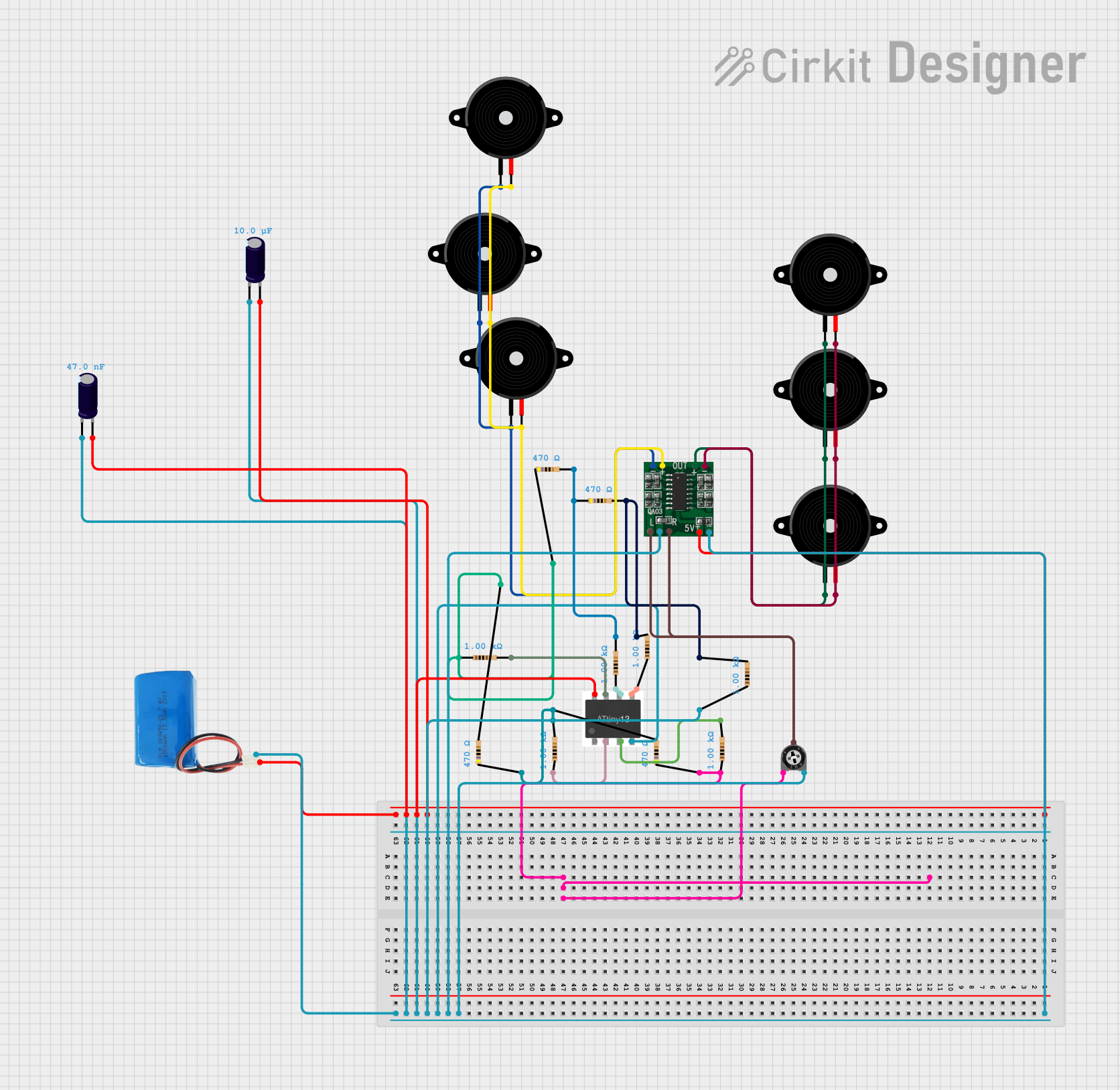
Circuit Documentation
Summary of the Circuit
This circuit appears to be an audio amplification system utilizing a PAM8403 amplifier IC to drive multiple Piezo speakers. An ATtiny microcontroller is included, likely for control purposes, although no code is provided. The circuit is powered by a 5V battery and includes various resistors and capacitors for stabilization and filtering. A trimmer potentiometer is used, possibly for volume control or signal adjustment.
Component List
PAM8403
- Description: A 3W, Class-D stereo audio amplifier.
- Purpose: Amplifies audio signals to drive Piezo speakers.
Piezo Speaker
- Description: An electronic device that can produce sound when an electrical signal is applied.
- Purpose: Outputs the audio signal in the form of sound waves.
ATtiny Microcontroller
- Description: A small, low-power CMOS 8-bit microcontroller.
- Purpose: Controls the audio signal processing and possibly other functions of the circuit.
5V Battery
- Description: A power source providing a 5V output.
- Purpose: Supplies power to the circuit.
Electrolytic Capacitor
- Description: A polarized capacitor with a larger capacitance.
- Purpose: Provides power supply filtering and decoupling.
Resistor
- Description: A passive two-terminal electrical component that implements electrical resistance.
- Purpose: Used for biasing, filtering, and setting operating points in the circuit.
Trimmer Potentiometer
- Description: A three-terminal resistor with an adjustable center tap.
- Purpose: Provides an adjustable voltage divider for signal level adjustment.
Wiring Details
PAM8403
- 5vIN+: Connected to the positive terminal of the 5V battery, VCC of ATtiny, and "+" pins of electrolytic capacitors.
- GND/IN-: Connected to the negative terminal of the 5V battery, GND of ATtiny, "-" pins of electrolytic capacitors, leg2 of the trimmer potentiometer, and pin1 of a 1000 Ohm resistor.
- R-INPUT: Connected to the wiper of the trimmer potentiometer.
- L-INPUT: Connected to the wiper of the trimmer potentiometer.
- L-: Connected to pin1 of multiple Piezo speakers.
- L+: Connected to pin2 of multiple Piezo speakers.
- R+: Connected to pin1 of multiple Piezo speakers.
- R-: Connected to pin2 of multiple Piezo speakers.
Piezo Speaker
- pin1: Connected to either L- or R+ of the PAM8403, depending on the speaker's channel.
- pin2: Connected to either L+ or R- of the PAM8403, depending on the speaker's channel.
ATtiny Microcontroller
- VCC: Connected to the positive terminal of the 5V battery and "+" pins of electrolytic capacitors.
- GND: Connected to the negative terminal of the 5V battery and "-" pins of electrolytic capacitors.
- PB3, PB4, PB0, PB1, PB2: Connected to one end of various resistors.
5V Battery
- positive: Connected to 5vIN+ of PAM8403, VCC of ATtiny, and "+" pins of electrolytic capacitors.
- negative: Connected to GND/IN- of PAM8403, GND of ATtiny, and "-" pins of electrolytic capacitors.
Electrolytic Capacitor
- +: Connected to the positive terminal of the 5V battery, VCC of ATtiny, and 5vIN+ of PAM8403.
- -: Connected to the negative terminal of the 5V battery, GND of ATtiny, and GND/IN- of PAM8403.
Resistor
- pin1: Connected to various pins of ATtiny or other resistors.
- pin2: Connected to various pins of ATtiny or other resistors.
Trimmer Potentiometer
- leg1: Connected to pin1 of two 470 Ohm resistors.
- wiper: Connected to R-INPUT and L-INPUT of PAM8403.
- leg2: Connected to GND/IN- of PAM8403.
Documented Code
No code has been provided for the ATtiny microcontroller. If code is later supplied, it should be documented here with explanations of its functionality and how it interacts with the circuit components.