
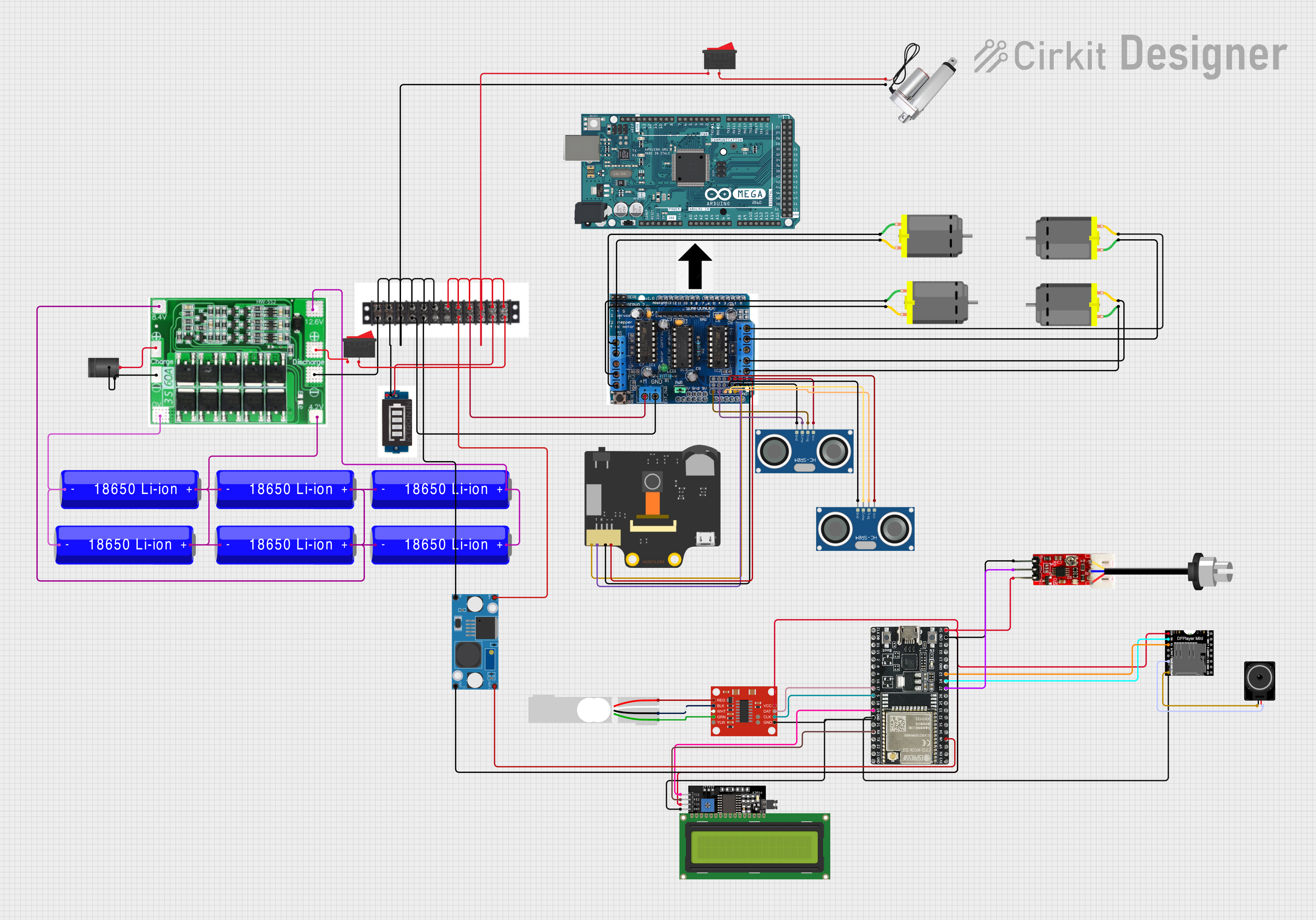
Circuit Documentation
Summary
This circuit is designed to manage and monitor a battery system using multiple 18650 Li-ion batteries, a 3S 60A BMS (Battery Management System), and various sensors and actuators. It includes an Arduino Mega 2560 for control logic, an ESP32-WROOM-32UE for additional processing and connectivity, and a range of components such as DC motors, ultrasonic sensors, a turbidity sensor, and a load cell with an amplifier. The circuit also features a battery level indicator, a DFPlayer Mini for audio output, an LCD display for user interface, and a motor driver shield for controlling the DC motors.
Component List
- 3S 60A BMS: A battery management system for managing a 3-cell series battery pack.
- 18650 Li-ion Battery: Rechargeable batteries used in the battery pack.
- 2.1mm DC Barrel Jack: A power connector for the circuit.
- Terminal Block: A connector for joining multiple wires together.
- Battery Level Indicator: Displays the charge level of the battery pack.
- Arduino Mega 2560: A microcontroller board based on the ATmega2560.
- Linear Actuator: A type of motor that creates motion in a straight line.
- Huskylens: An AI camera module for object recognition and tracking.
- HC-SR04 Ultrasonic Sensor: A sensor for measuring distance via ultrasonic waves.
- DC Motor: An electric motor that runs on direct current electricity.
- ESP32-WROOM-32UE: A powerful microcontroller with Wi-Fi and Bluetooth capabilities.
- Load Cell - Red/white/black/green: A sensor that measures force or weight.
- SparkFun Load Cell Amplifier - HX711: An amplifier for the load cell signal.
- LCD Display 16x4 I2C: A 16x4 character LCD display with an I2C interface.
- DFPlayer MINI: A small and low-cost MP3 module with a simplified output.
- Loudspeaker: An electroacoustic transducer that converts an electrical audio signal into sound.
- LM2596 Step Down Module: A voltage regulator that steps down input voltage to a lower output voltage.
- Rocker Switch: A switch that rocks back and forth to open or close the circuit.
- L293D Motor Driver Shield: A shield for Arduino that can control up to four DC motors with 8-bit speed control.
Wiring Details
3S 60A BMS
- Positive: Connected to the center pin of the 2.1mm DC Barrel Jack and one terminal of the Rocker Switch.
- Negative: Connected to the switch and sleeve pins of the 2.1mm DC Barrel Jack, the negative terminal of the Terminal Block, and another terminal of the Rocker Switch.
18650 Li-ion Battery
- Multiple batteries are connected in series and parallel to form a battery pack managed by the 3S 60A BMS.
2.1mm DC Barrel Jack
- Center: Connected to the positive of the 3S 60A BMS.
- Switch: Connected to the negative of the 3S 60A BMS.
- Sleeve: Connected to the negative of the 3S 60A BMS.
Terminal Block
- Positive (+): Connected to the positive of the 3S 60A BMS, LM2596 Step Down Module IN+, L293D Motor Driver Shield, Battery Level Indicator, and Rocker Switch.
- Negative (-): Connected to the negative of the 3S 60A BMS, LM2596 Step Down Module IN-, L293D Motor Driver Shield, Linear Actuator, and Battery Level Indicator.
Battery Level Indicator
- Positive: Connected to the positive terminal of the Terminal Block.
- GND: Connected to the negative terminal of the Terminal Block.
Arduino Mega 2560
- No specific wiring provided.
Linear Actuator
- Positive (+): Connected to the Rocker Switch.
- Negative (-): Connected to the negative terminal of the Terminal Block.
Huskylens
- SDA: Connected to A4 on the L293D Motor Driver Shield.
- SCL: Connected to A5 on the L293D Motor Driver Shield.
- GND: Connected to GND on the L293D Motor Driver Shield.
- VCC: Connected to 5+ on the L293D Motor Driver Shield.
HC-SR04 Ultrasonic Sensor
- VCC: Connected to 5+ on the L293D Motor Driver Shield.
- TRIG: Connected to A0 and A2 on the L293D Motor Driver Shield (two sensors).
- ECHO: Connected to A1 and A3 on the L293D Motor Driver Shield (two sensors).
- GND: Connected to GND on the L293D Motor Driver Shield.
DC Motor
- Pin 1 and Pin 2: Connected to the L293D Motor Driver Shield (specific connections not provided).
ESP32-WROOM-32UE
- VN: Connected to OUT+ on the LM2596 Step Down Module.
- 27: Connected to OUT on the Turbidity Module.
- 14: Connected to RX on the DFPlayer MINI.
- 12: Connected to TX on the DFPlayer MINI.
- GND: Connected to OUT- on the LM2596 Step Down Module, GND on the Turbidity Module, and GND on the DFPlayer MINI.
Load Cell - Red/white/black/green
- E+: Connected to RED on the SparkFun Load Cell Amplifier - HX711.
- A-: Connected to WHT on the SparkFun Load Cell Amplifier - HX711.
- E-: Connected to BLK on the SparkFun Load Cell Amplifier - HX711.
- A+: Connected to GRN on the SparkFun Load Cell Amplifier - HX711.
SparkFun Load Cell Amplifier - HX711
- VCC: Connected to 5V on the ESP32-WROOM-32UE.
- GND: Connected to GND on the ESP32-WROOM-32UE.
- CLK: Connected to pin 5 on the ESP32-WROOM-32UE.
- DAT: Connected to pin 17 on the ESP32-WROOM-32UE.
LCD Display 16x4 I2C
- SCL: Connected to pin 19 on the ESP32-WROOM-32UE.
- SDA: Connected to RX on the ESP32-WROOM-32UE.
- VCC: Connected to 5V on the ESP32-WROOM-32UE.
- GND: Connected to GND on the ESP32-WROOM-32UE.
DFPlayer MINI
- VCC: Connected to 5V on the ESP32-WROOM-32UE.
- RX: Connected to pin 14 on the ESP32-WROOM-32UE.
- TX: Connected to pin 12 on the ESP32-WROOM-32UE.
- GND: Connected to GND on the ESP32-WROOM-32UE.
- SPK1: Connected to pin2 on the Loudspeaker.
- SPK2: Connected to pin1 on the Loudspeaker.
Loudspeaker
- Pin1: Connected to SPK2 on the DFPlayer MINI.
- Pin2: Connected to SPK1 on the DFPlayer MINI.
LM2596 Step Down Module
- IN+: Connected to the positive terminal of the Terminal Block.
- IN-: Connected to the negative terminal of the Terminal Block.
- OUT+: Connected to VN on the ESP32-WROOM-32UE.
- OUT-: Connected to GND on the ESP32-WROOM-32UE.
Rocker Switch
- Terminal 1: Connected to the positive of the 3S 60A BMS and the positive terminal of the Terminal Block.
- Terminal 2: Connected to the Linear Actuator and the negative of the 3S 60A BMS.
L293D Motor Driver Shield
- 5+: Provides power to the Huskylens, HC-SR04 Ultrasonic Sensors, and ESP32-WROOM-32UE.
- GND: Common ground for Huskylens, HC-SR04 Ultrasonic Sensors, and ESP32-WROOM-32UE.
- A0-A5: Control signals for Huskylens and HC-SR04 Ultrasonic Sensors.
Documented Code
Arduino Mega 2560 (sketch.ino)
void setup() {
  // put your setup code here, to run once:

}

void loop() {
  // put your main code here, to run repeatedly:

}
Note: The provided code for the Arduino Mega 2560 is a template with empty setup and loop functions. Actual implementation code is required for the circuit to perform any operations.
ESP32-WROOM-32UE
No code provided for the ESP32-WROOM-32UE.