Cirkit Designer
Your all-in-one circuit design IDE
Home /
Project Documentation
Dual Motor Control Circuit with Directional Switches

Circuit Documentation
Summary of the Circuit
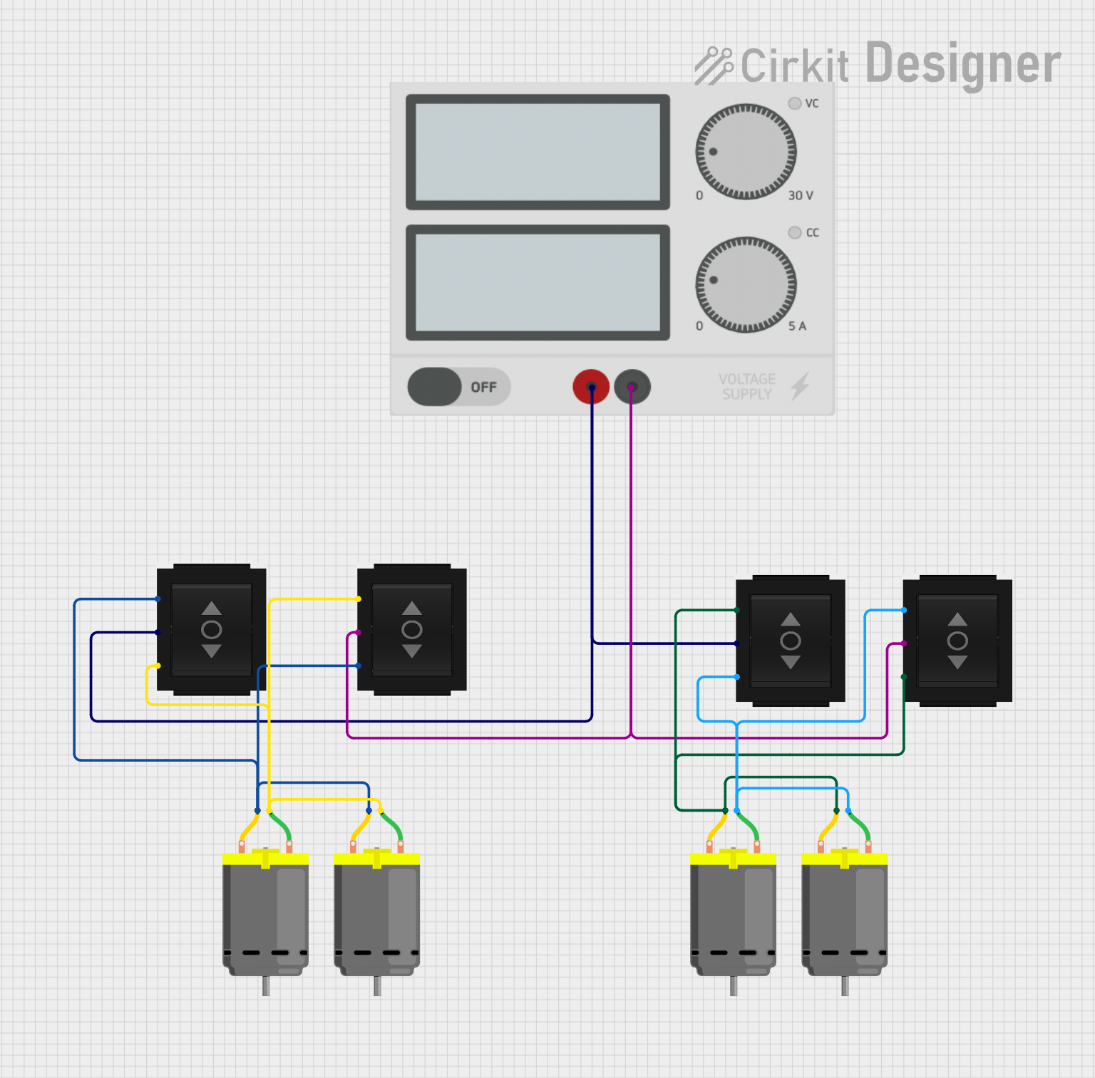
The circuit described by the provided inputs consists of multiple DC motors, directional switches, and a power supply. The DC motors are controlled by the directional switches, which allow for changing the direction of the motor rotation. The power supply provides the necessary voltage and current to drive the motors. The circuit does not include any microcontrollers or embedded code.
Component List
DC Motor
- Description: A DC motor is an electric motor that runs on direct current (DC) electricity.
- Pins:
- pin 1: Motor positive terminal
- pin 2: Motor negative terminal
Directional Switch
- Description: A directional switch is used to change the direction of current flow, which in turn changes the direction of motor rotation.
- Pins:
- IN: Input from power supply
- Out 1: Output to one terminal of the motor or another switch
- Out 2: Output to the other terminal of the motor or another switch
Power Supply
- Description: Provides the electrical power to the circuit.
- Pins:
- +: Positive voltage output
- -: Ground or negative voltage output
Wiring Details
DC Motor
- Motor 1:
- pin 1 is connected to Out 1 of Directional Switch 3
- pin 2 is connected to Out 2 of Directional Switch 3
- Motor 2:
- pin 1 is connected to Out 1 of Directional Switch 1
- pin 2 is connected to Out 2 of Directional Switch 1
- Motor 3:
- pin 1 is connected to Out 1 of Directional Switch 4
- pin 2 is connected to Out 2 of Directional Switch 4
- Motor 4:
- pin 1 is connected to Out 1 of Directional Switch 2
- pin 2 is connected to Out 2 of Directional Switch 2
Directional Switch
- Switch 1:
- IN is connected to the positive terminal of the Power Supply
- Out 1 is connected to pin 1 of Motor 1 and Motor 2
- Out 2 is connected to pin 2 of Motor 1 and Motor 2
- Switch 2:
- IN is connected to the negative terminal of the Power Supply
- Out 1 is connected to pin 1 of Motor 3 and Motor 4
- Out 2 is connected to pin 2 of Motor 3 and Motor 4
- Switch 3:
- IN is connected to the positive terminal of the Power Supply
- Out 1 is connected to pin 1 of Motor 1
- Out 2 is connected to pin 2 of Motor 1
- Switch 4:
- IN is connected to the negative terminal of the Power Supply
- Out 1 is connected to pin 1 of Motor 3
- Out 2 is connected to pin 2 of Motor 3
Power Supply
- Power Supply:
- is connected to IN of Switch 1 and Switch 3
- is connected to IN of Switch 2 and Switch 4
Documented Code
There is no embedded code provided for this circuit. The circuit operates purely on the basis of the hardware components and their wiring without the need for software control.