
Circuit Documentation
Summary
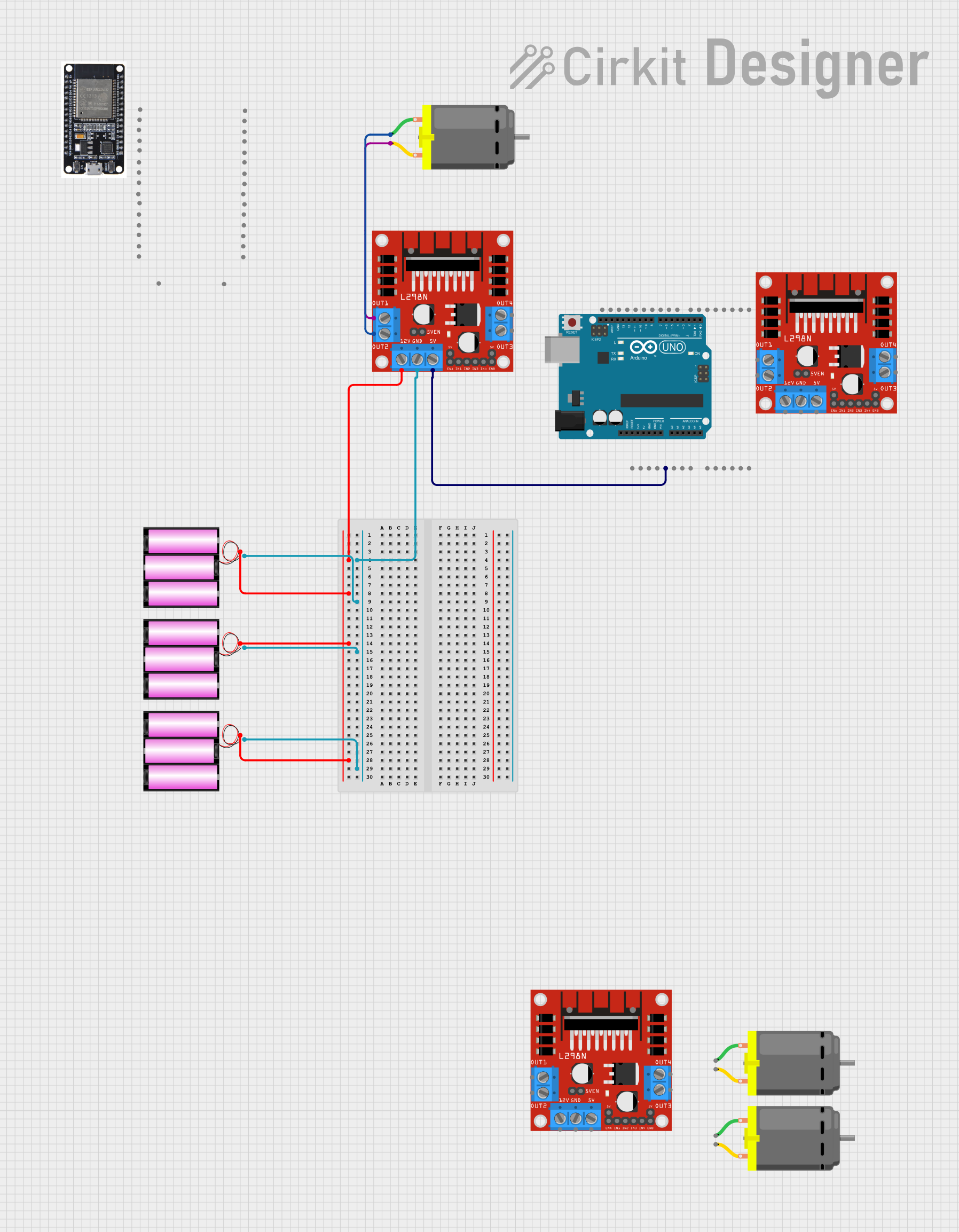
This document provides a detailed overview of a circuit that includes multiple L298N DC motor drivers, DC motors, 12V batteries, an Arduino UNO, and an ESP32. The circuit is designed to control DC motors using the L298N motor drivers, powered by 12V batteries, and managed by an Arduino UNO microcontroller. The ESP32 is included for additional functionality.
Component List
L298N DC Motor Driver
- Description: A dual H-Bridge motor driver that allows control of the speed and direction of two DC motors.
- Pins: OUT1, OUT2, 12V, GND, 5V, OUT3, OUT4, 5V-ENA-JMP-I, 5V-ENA-JMP-O, +5V-J1, +5V-J2, ENA, IN1, IN2, IN3, IN4, ENB
DC Motor
- Description: A simple DC motor with two pins for power and ground.
- Pins: pin 1, pin 2
Battery 12V
- Description: A 12V battery used to power the motor drivers and motors.
- Pins: +, -
Arduino UNO
- Description: A microcontroller board based on the ATmega328P, used for controlling the motor drivers.
- Pins: UNUSED, IOREF, Reset, 3.3V, 5V, GND, Vin, A0, A1, A2, A3, A4, A5, SCL, SDA, AREF, D13, D12, D11, D10, D9, D8, D7, D6, D5, D4, D3, D2, D1, D0
ESP32
- Description: A low-cost, low-power system on a chip (SoC) with Wi-Fi and Bluetooth capabilities.
- Pins: EN, VP, VN, D34, D35, D32, D33, D25, D26, D27, D14, D12, D13, GND, VIN, 3V3, D15, D2, D4, RX2, TX2, D5, D18, D19, D21, RX0, TX0, D22, D23, BOOT
Wiring Details
L298N DC Motor Driver 1
- 12V: Connected to the positive terminal of three 12V batteries.
- GND: Connected to the negative terminal of three 12V batteries.
- OUT1: Connected to pin 2 of DC Motor 1.
- OUT2: Connected to pin 1 of DC Motor 1.
- 5V: Connected to the 5V pin of the Arduino UNO.
L298N DC Motor Driver 2
- 12V: Not connected in this circuit.
- GND: Not connected in this circuit.
- OUT1: Not connected in this circuit.
- OUT2: Not connected in this circuit.
- 5V: Not connected in this circuit.
L298N DC Motor Driver 3
- 12V: Not connected in this circuit.
- GND: Not connected in this circuit.
- OUT1: Not connected in this circuit.
- OUT2: Not connected in this circuit.
- 5V: Not connected in this circuit.
DC Motor 1
- pin 1: Connected to OUT2 of L298N DC Motor Driver 1.
- pin 2: Connected to OUT1 of L298N DC Motor Driver 1.
DC Motor 2
- pin 1: Not connected in this circuit.
- pin 2: Not connected in this circuit.
DC Motor 3
- pin 1: Not connected in this circuit.
- pin 2: Not connected in this circuit.
Battery 12V 1
- +: Connected to the 12V pin of L298N DC Motor Driver 1.
- -: Connected to the GND pin of L298N DC Motor Driver 1.
Battery 12V 2
- +: Connected to the 12V pin of L298N DC Motor Driver 1.
- -: Connected to the GND pin of L298N DC Motor Driver 1.
Battery 12V 3
- +: Connected to the 12V pin of L298N DC Motor Driver 1.
- -: Connected to the GND pin of L298N DC Motor Driver 1.
Arduino UNO
- 5V: Connected to the 5V pin of L298N DC Motor Driver 1.
ESP32
- Pins: Not connected in this circuit.
Documented Code
Arduino UNO Code
void setup() {
  // put your setup code here, to run once:

}

void loop() {
  // put your main code here, to run repeatedly:

}
Additional Documentation
// No additional documentation provided.
This document provides a comprehensive overview of the circuit, including the components used, their connections, and the code running on the Arduino UNO.