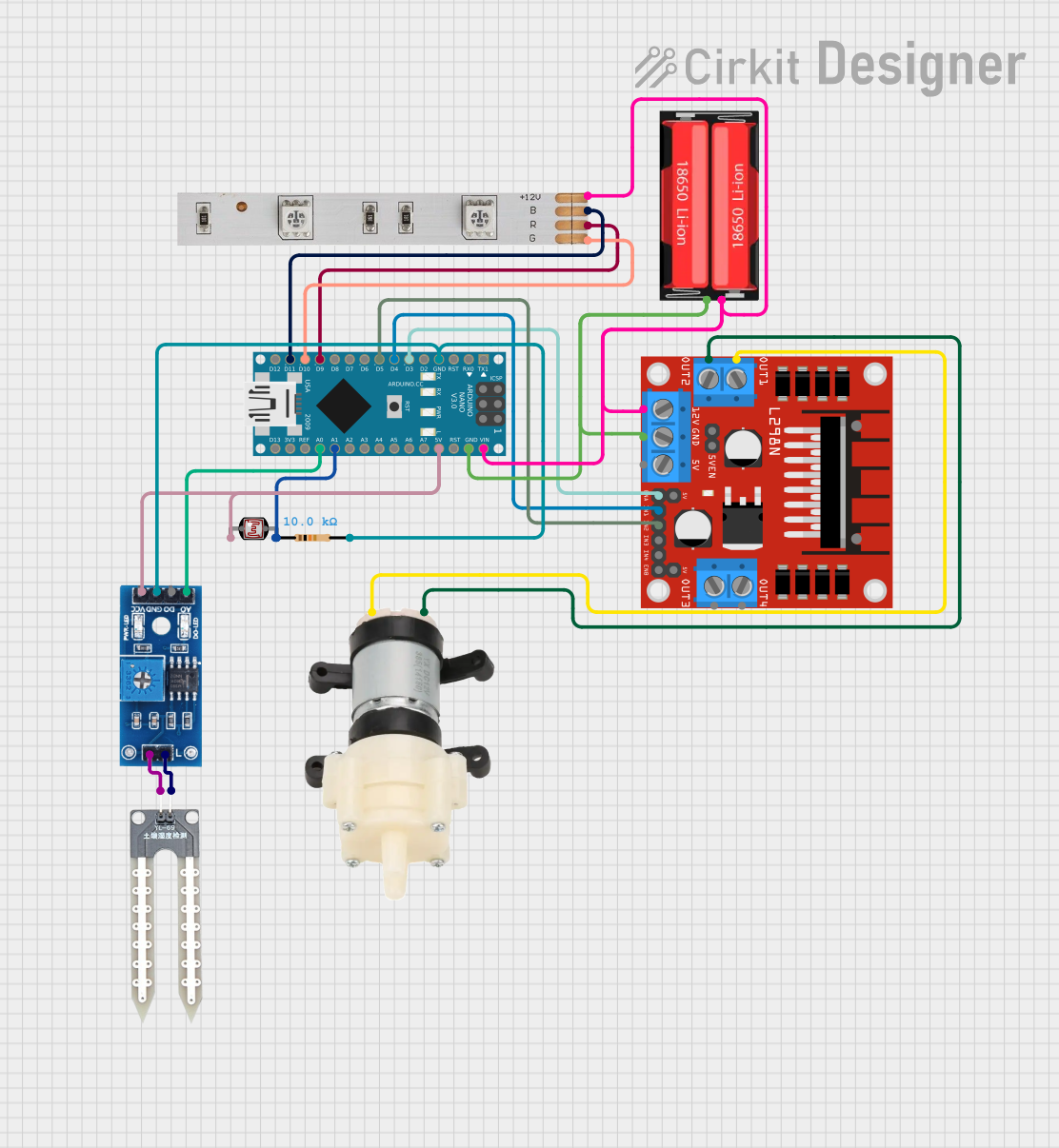
Arduino Nano-Controlled Environmental Monitoring System with LED Indicators and Water Pump

Circuit Documentation
Summary of the Circuit
This circuit is designed to control a mini diaphragm water pump using an Arduino Nano microcontroller and an L298N DC motor driver. It also includes an LED strip for visual feedback and various sensors for environmental monitoring, such as a photocell (LDR) for light detection, a water sensor, and a rain/snow sensor. The power is supplied by an 18650 Li-Ion battery, and a resistor is used in conjunction with the LDR to form a voltage divider for light level sensing.
Component List
Arduino Nano
- Microcontroller board based on the ATmega328P
- It has a variety of digital and analog I/O pins.
LED Strip
- A strip of LEDs that can be controlled to display various colors.
- It has pins for Red, Green, Blue, and +12V power supply.
L298N DC Motor Driver
- A module capable of driving DC motors with directional and speed control.
- It has pins for motor outputs, power supply, and control inputs.
Mini Diaphragm Water Pump
- A pump used for moving water.
- It has two pins for power supply: Positive (+) and Negative (-).
Photocell (LDR)
- A light-dependent resistor whose resistance changes with light intensity.
- It has two pins for connecting to a circuit.
Resistor
- A passive component used to limit current or divide voltages.
- It has a resistance value of 10,000 Ohms.
Water Sensor
- A sensor used to detect the presence of water.
- It has two pins for power supply and signal output.
Rain/Snow Sensor - Board
- A sensor used to detect rain or snowfall.
- It has pins for analog and digital signal outputs, power supply, and ground.
18650 Li-Ion Battery
- A rechargeable battery used to power the circuit.
- It has two pins: Positive and Negative.
Wiring Details
Arduino Nano
- GND connected to the common ground net.
- D3 connected to L298N DC motor driver ENA.
- D4 connected to L298N DC motor driver IN1.
- D5 connected to L298N DC motor driver IN2.
- D9 connected to LED Strip Red.
- D10 connected to LED Strip Green.
- D11/MOSI connected to LED Strip Blue.
- VIN connected to the +12V net from the L298N DC motor driver and LED Strip.
- 5V connected to Rain/Snow Sensor - Board VCC (5V) and Photocell (LDR) pin 0.
- A1 connected to one side of the Resistor, which forms a voltage divider with the Photocell (LDR).
- A0 connected to Rain/Snow Sensor - Board A0 (Analog).
LED Strip
- R, G, B connected to Arduino Nano D9, D10, D11/MOSI respectively for color control.
- +12V connected to the +12V power net.
L298N DC Motor Driver
- ENA, IN1, IN2 connected to Arduino Nano D3, D4, D5 for motor control.
- 12V connected to the +12V power net.
- GND connected to the common ground net.
- OUT1, OUT2 connected to Mini Diaphragm Water Pump Negative (-) and Positive (+) for driving the pump.
Mini Diaphragm Water Pump
- Positive (+) and Negative (-) connected to L298N DC motor driver OUT2 and OUT1 for power.
Photocell (LDR)
- Pin 0 connected to Arduino Nano 5V.
- Pin 1 connected to one side of the Resistor, forming a voltage divider.
Resistor
- Pin1 connected to Photocell (LDR) pin 1 and Arduino Nano A1.
- Pin2 connected to the common ground net.
Water Sensor
- (Negative) connected to Rain/Snow Sensor - Board pin 1.
- (Positive) connected to Rain/Snow Sensor - Board pin 2.
Rain/Snow Sensor - Board
- GND connected to the common ground net.
- VCC (5V) connected to Arduino Nano 5V.
- A0 (Analog) connected to Arduino Nano A0.
- 1, 2 connected to Water Sensor - and + respectively.
18650 Li-Ion Battery
- Positive connected to the +12V power net.
- Negative connected to the common ground net.
Documented Code
void setup() {
  // put your setup code here, to run once:

}

void loop() {
  // put your main code here, to run repeatedly:

}
The provided code is a template with empty setup() and loop() functions, which are the entry points for Arduino code. The setup() function is called once when the microcontroller starts, and the loop() function is called repeatedly, allowing the microcontroller to perform operations based on the circuit's design and sensor inputs. The actual implementation of the control logic for the motor driver, LED strip, and sensor readings should be added to these functions.