
Arduino UNO-Based Quadcopter with Ultrasonic Sensors and Brushless Motors
View and Edit Project In Cirkit Designer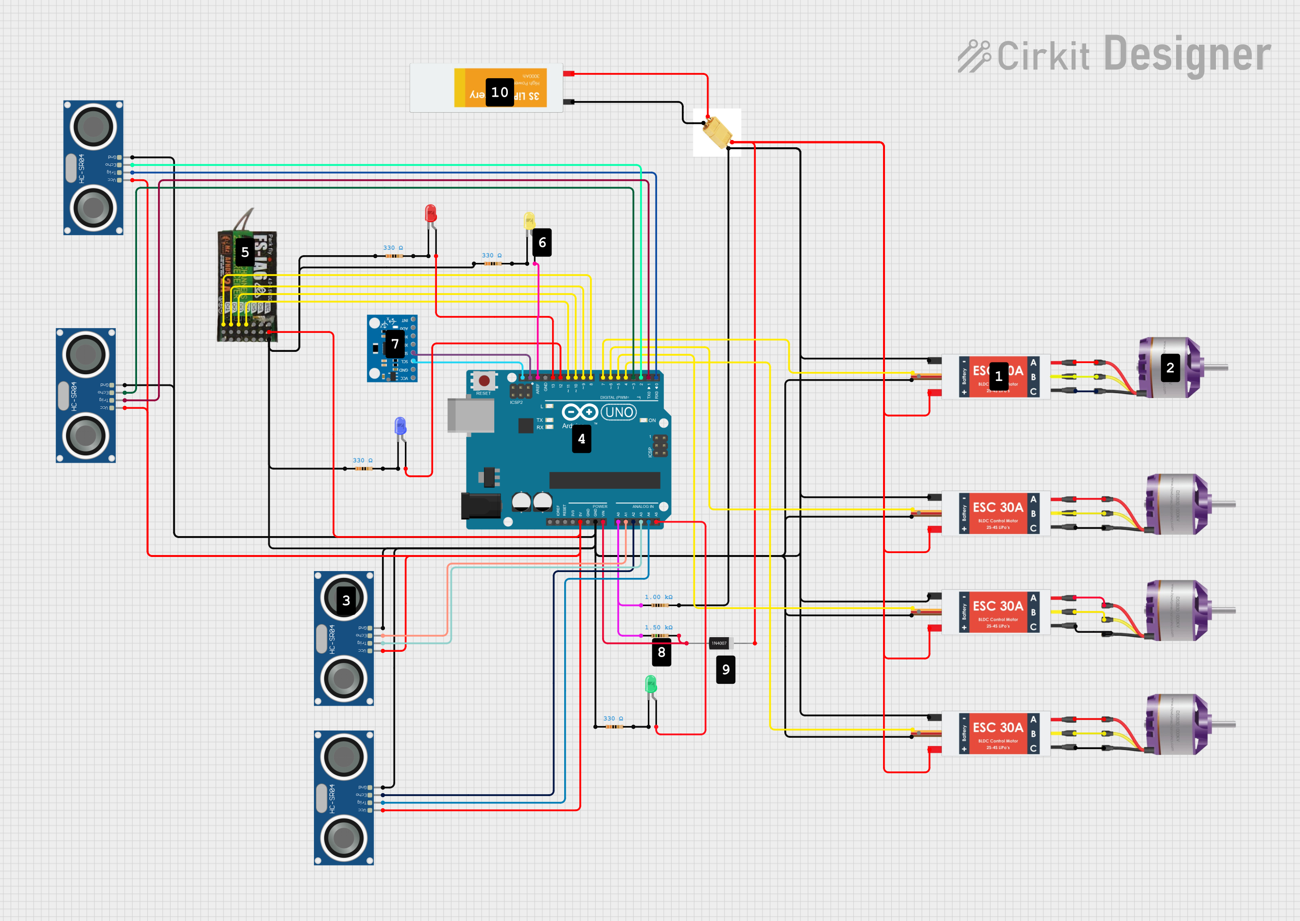
Circuit Documentation
Summary
This document provides a detailed overview of a circuit design that includes various components such as Electronic Speed Controllers (ESCs), Brushless Motors, Ultrasonic Sensors, LEDs, Resistors, an MPU6050 sensor, an Arduino UNO, and a FLYSKY FS-IA6 receiver. The circuit is designed to control multiple brushless motors using ESCs, measure distances using ultrasonic sensors, and provide visual feedback using LEDs. The Arduino UNO serves as the central microcontroller, interfacing with all other components.
Component List
Electronic Speed Controller (ESC)
- Description: Controls the speed of brushless motors.
- Pins: Battery VCC, Battery GND, Signal, 5V out, GND out, M1, M2, M3
Brushless Motor
- Description: High-efficiency motor used in various applications.
- Pins: L1, L2, L3
HC-SR04 Ultrasonic Sensor
- Description: Measures distance using ultrasonic waves.
- Pins: VCC, TRIG, ECHO, GND
XT60 Connector
- Description: High-current connector for batteries.
- Pins: Positif output, Negatif output, Positif input, Negatif Input
LED: Two Pin (Red)
- Description: Red LED for visual indication.
- Pins: Cathode, Anode
LED: Two Pin (Yellow)
- Description: Yellow LED for visual indication.
- Pins: Cathode, Anode
LED: Two Pin (Blue)
- Description: Blue LED for visual indication.
- Pins: Cathode, Anode
LED: Two Pin (Green)
- Description: Green LED for visual indication.
- Pins: Cathode, Anode
1N4007 Rectifier Diode
- Description: General-purpose rectifier diode.
- Pins: Cathode, Anode
Resistor
- Description: Limits current flow in the circuit.
- Pins: Pin1, Pin2
- Properties:
- Resistance: 1000 Ohms
- Resistance: 330 Ohms
- Resistance: 1500 Ohms
FLYSKY FS-IA6
- Description: 6-channel receiver for remote control systems.
- Pins: CH1, 5V, GND, CH2, CH3, CH4, CH5, CH6, VCC
MPU6050
- Description: 6-axis motion tracking device.
- Pins: VCC, GND, SCL, SDA, XDA, XCL, AD0, INT, 3.3V
Lipo Battery
- Description: Rechargeable lithium polymer battery.
- Pins: VCC, GND
Arduino UNO
- Description: Microcontroller board based on the ATmega328P.
- Pins: UNUSED, IOREF, Reset, 3.3V, 5V, GND, Vin, A0, A1, A2, A3, A4, A5, SCL, SDA, AREF, D13, D12, D11, D10, D9, D8, D7, D6, D5, D4, D3, D2, D1, D0
Wiring Details
Electronic Speed Controller (ESC)
- Battery VCC: Connected to XT60 Connector (positif output)
- Battery GND: Connected to XT60 Connector (Negatif output)
- Signal: Connected to Arduino UNO (D7, D6, D5, D4)
- 5V out: Not connected
- GND out: Connected to common ground
- M1: Connected to Brushless Motor (L1)
- M2: Connected to Brushless Motor (L2)
- M3: Connected to Brushless Motor (L3)
Brushless Motor
- L1: Connected to ESC (M1)
- L2: Connected to ESC (M2)
- L3: Connected to ESC (M3)
HC-SR04 Ultrasonic Sensor
- VCC: Connected to Arduino UNO (5V)
- TRIG: Connected to Arduino UNO (A3, A4, D1, D0)
- ECHO: Connected to Arduino UNO (A1, A2, D3, D2)
- GND: Connected to common ground
XT60 Connector
- Positif output: Connected to ESC (Battery VCC)
- Negatif output: Connected to ESC (Battery GND)
- Positif input: Connected to Lipo Battery (VCC)
- Negatif Input: Connected to Lipo Battery (GND)
LED: Two Pin (Red)
- Anode: Connected to Arduino UNO (D13)
- Cathode: Connected to Resistor (pin2)
LED: Two Pin (Yellow)
- Anode: Connected to Arduino UNO (AREF)
- Cathode: Connected to Resistor (pin2)
LED: Two Pin (Blue)
- Anode: Connected to Arduino UNO (D12)
- Cathode: Connected to Resistor (pin2)
LED: Two Pin (Green)
- Anode: Connected to Arduino UNO (A5)
- Cathode: Connected to Resistor (pin2)
1N4007 Rectifier Diode
- Anode: Connected to Resistor (pin2)
- Cathode: Connected to XT60 Connector (positif output)
Resistor
- Pin1: Connected to common ground
- Pin2: Connected to various LEDs and 1N4007 Rectifier Diode
FLYSKY FS-IA6
- CH1: Connected to Arduino UNO (D8)
- 5V: Connected to Arduino UNO (5V)
- GND: Connected to common ground
- CH2: Connected to Arduino UNO (D9)
- CH3: Connected to Arduino UNO (D10)
- CH4: Connected to Arduino UNO (D11)
- CH5: Not connected
- CH6: Not connected
- VCC: Not connected
MPU6050
- VCC: Connected to Arduino UNO (5V)
- GND: Connected to common ground
- SCL: Connected to Arduino UNO (SCL)
- SDA: Connected to Arduino UNO (SDA)
- XDA: Not connected
- XCL: Not connected
- AD0: Not connected
- INT: Not connected
- 3.3V: Not connected
Lipo Battery
- VCC: Connected to XT60 Connector (Positif input)
- GND: Connected to XT60 Connector (Negatif Input)
Arduino UNO
- 5V: Connected to various components (HC-SR04 Ultrasonic Sensor, FLYSKY FS-IA6, MPU6050)
- GND: Connected to common ground
- Vin: Connected to Resistor (pin2)
- A0: Connected to Resistor (pin1)
- A1: Connected to HC-SR04 Ultrasonic Sensor (ECHO)
- A2: Connected to HC-SR04 Ultrasonic Sensor (ECHO)
- A3: Connected to HC-SR04 Ultrasonic Sensor (TRIG)
- A4: Connected to HC-SR04 Ultrasonic Sensor (TRIG)
- A5: Connected to LED (Green) (Anode)
- SCL: Connected to MPU6050 (SCL)
- SDA: Connected to MPU6050 (SDA)
- AREF: Connected to LED (Yellow) (Anode)
- D13: Connected to LED (Red) (Anode)
- D12: Connected to LED (Blue) (Anode)
- D11: Connected to FLYSKY FS-IA6 (CH4)
- D10: Connected to FLYSKY FS-IA6 (CH3)
- D9: Connected to FLYSKY FS-IA6 (CH2)
- D8: Connected to FLYSKY FS-IA6 (CH1)
- D7: Connected to ESC (Signal)
- D6: Connected to ESC (Signal)
- D5: Connected to ESC (Signal)
- D4: Connected to ESC (Signal)
- D3: Connected to HC-SR04 Ultrasonic Sensor (ECHO)
- D2: Connected to HC-SR04 Ultrasonic Sensor (ECHO)
- D1: Connected to HC-SR04 Ultrasonic Sensor (TRIG)
- D0: Connected to HC-SR04 Ultrasonic Sensor (TRIG)
Documented Code
Arduino UNO Code
void setup() {
  // put your setup code here, to run once:

}

void loop() {
  // put your main code here, to run repeatedly:

}
1N4007 Rectifier Diode Code
void setup() {
  // put your setup code here, to run once:

}

void loop() {
  // put your main code here, to run repeatedly:

}
Brushless Motor Code
void setup() {
  // put