
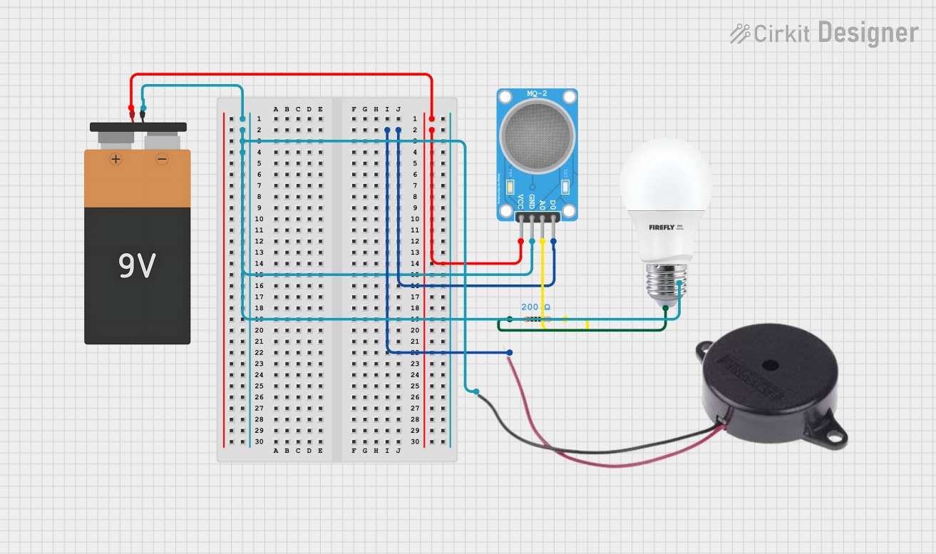
Circuit Documentation
Summary of the Circuit
This circuit consists of a 9V battery, a buzzer, a resistor, a bulb, and an MQ-2 gas sensor. The battery provides power to the circuit. The buzzer is an output device that can be triggered by the digital output (D0) of the MQ-2 sensor. The bulb is connected in series with a resistor, which limits the current through the bulb. The MQ-2 sensor is used to detect gases in the environment and provides both analog (A0) and digital (D0) signals.
Component List
Battery 9V
- Description: A standard 9V battery used as the power source for the circuit.
- Pins: VCC, GND
Buzzer
- Description: An audio signaling device.
- Pins: POSITIVE, NEGATIVE
Resistor
- Description: A passive two-terminal electrical component that implements electrical resistance as a circuit element.
- Properties: 200 Ohms resistance
- Pins: pin1, pin2
Bulb
- Description: An electric light with a wire filament heated until it glows.
- Pins: +, -
MQ-2 Sensor
- Description: A gas sensor used for detecting a wide range of gases including LPG, smoke, and alcohol.
- Pins: VCC, GND, A0, D0
Wiring Details
Battery 9V
- VCC connected to:
- MQ-2 Sensor VCC
- GND connected to:
- Buzzer NEGATIVE
- Bulb -
- MQ-2 Sensor GND
Buzzer
- POSITIVE connected to:
- MQ-2 Sensor D0
- NEGATIVE connected to:
- Battery 9V GND
Resistor
- pin1 connected to:
- Bulb +
- pin2 connected to:
- MQ-2 Sensor A0
Bulb
-
- connected to:
- Resistor pin1
-
- connected to:
- Battery 9V GND
MQ-2 Sensor
- VCC connected to:
- Battery 9V VCC
- GND connected to:
- Battery 9V GND
- A0 connected to:
- Resistor pin2
- D0 connected to:
- Buzzer POSITIVE
Documented Code
There is no microcontroller code provided for this circuit. If a microcontroller were to be included, it would likely interface with the MQ-2 sensor's A0 and D0 pins to process the sensor readings and control the buzzer or other output devices accordingly.