
ESP8266 NodeMCU Controlled Environment Monitoring System with Stepper Motor and Sensors
View and Edit Project In Cirkit Designer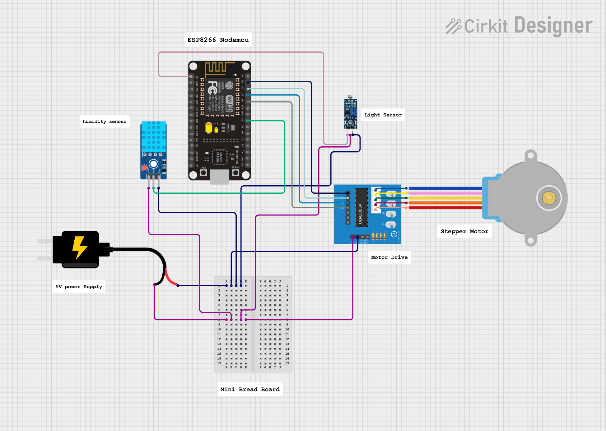
Circuit Documentation
Summary
This circuit integrates various components to perform a set of functions controlled by an ESP8266 NodeMCU microcontroller. The circuit includes a DHT11 temperature and humidity sensor, an LDR (Light Dependent Resistor) module for light sensing, a 28BYJ-48 stepper motor for motion control, and a ULN2003A breakout board to drive the stepper motor. The circuit is powered by a 5V DC source, which supplies power to the sensors, the motor driver, and the microcontroller.
Component List
ESP8266 NodeMCU
- Description: A Wi-Fi capable microcontroller module based on the ESP8266 chip.
- Pins: D0, D1, D2, D3, D4, 3V3, GND, D5, D6, D7, D8, RX, TX, A0, RSV, SD3, SD2, SD1, CMD, SD0, CLK, EN, RST, VIN
28BYJ-48 Stepper Motor
- Description: A small, 5-wire, unipolar stepper motor.
- Pins: BLUE, PINK, YELLOW, ORANGE, RED
ULN2003A Breakout Board
- Description: A breakout board for the ULN2003A transistor array IC, used for driving stepper motors.
- Pins: In 1, In 2, In 3, In 4, In 5, In 6, In 7, 0V, +5V, ON/OFF jumper switch, BLUE wire, PINK wire, YELLOW wire, ORANGE wire, RED wire
LDR Module 3 Pin
- Description: A module with a light-dependent resistor that outputs a digital signal.
- Pins: VCC, GND, DO
DHT11 Sensor V2
- Description: A digital temperature and humidity sensor.
- Pins: GND, DAT, VCC
DC Source 5V
- Description: A power supply module that provides a 5V output.
- Pins: VCC, GND
Wiring Details
ESP8266 NodeMCU
- D1 connected to ULN2003A breakout board In 1
- D2 connected to ULN2003A breakout board In 2
- D3 connected to ULN2003A breakout board In 3
- D4 connected to ULN2003A breakout board In 4
- D5 connected to DHT11 Sensor V2 DAT
- A0 connected to LDR Module 3 pin DO
- 3V3 (Not connected)
- GND (Not connected)
- D0, D6, D7, D8, RX, TX, RSV, SD3, SD2, SD1, CMD, SD0, CLK, EN, RST, VIN (Not connected)
28BYJ-48 Stepper Motor
- BLUE connected to ULN2003A breakout board BLUE wire
- PINK connected to ULN2003A breakout board PINK wire
- YELLOW connected to ULN2003A breakout board YELLOW wire
- ORANGE connected to ULN2003A breakout board ORANGE wire
- RED connected to ULN2003A breakout board RED wire
ULN2003A Breakout Board
- In 1 connected to ESP8266 NodeMCU D1
- In 2 connected to ESP8266 NodeMCU D2
- In 3 connected to ESP8266 NodeMCU D3
- In 4 connected to ESP8266 NodeMCU D4
- +5V connected to DC Source 5V VCC
- 0V connected to DC Source 5V GND
- BLUE wire connected to 28BYJ-48 Stepper Motor BLUE
- PINK wire connected to 28BYJ-48 Stepper Motor PINK
- YELLOW wire connected to 28BYJ-48 Stepper Motor YELLOW
- ORANGE wire connected to 28BYJ-48 Stepper Motor ORANGE
- RED wire connected to 28BYJ-48 Stepper Motor RED
- In 5, In 6, In 7, ON/OFF jumper switch (Not connected)
LDR Module 3 Pin
- VCC connected to DC Source 5V VCC
- GND connected to DC Source 5V GND
- DO connected to ESP8266 NodeMCU A0
DHT11 Sensor V2
- VCC connected to DC Source 5V VCC
- GND connected to DC Source 5V GND
- DAT connected to ESP8266 NodeMCU D5
DC Source 5V
- VCC connected to ULN2003A breakout board +5V, DHT11 Sensor V2 VCC, LDR Module 3 pin VCC
- GND connected to ULN2003A breakout board 0V, DHT11 Sensor V2 GND, LDR Module 3 pin GND
Documented Code
Since no code was provided in the input, this section is left blank. Normally, this section would include the source code for the microcontroller, along with comments explaining the functionality of the code and how it interacts with the connected components.