Cirkit Designer
Your all-in-one circuit design IDE
Home /
Project Documentation
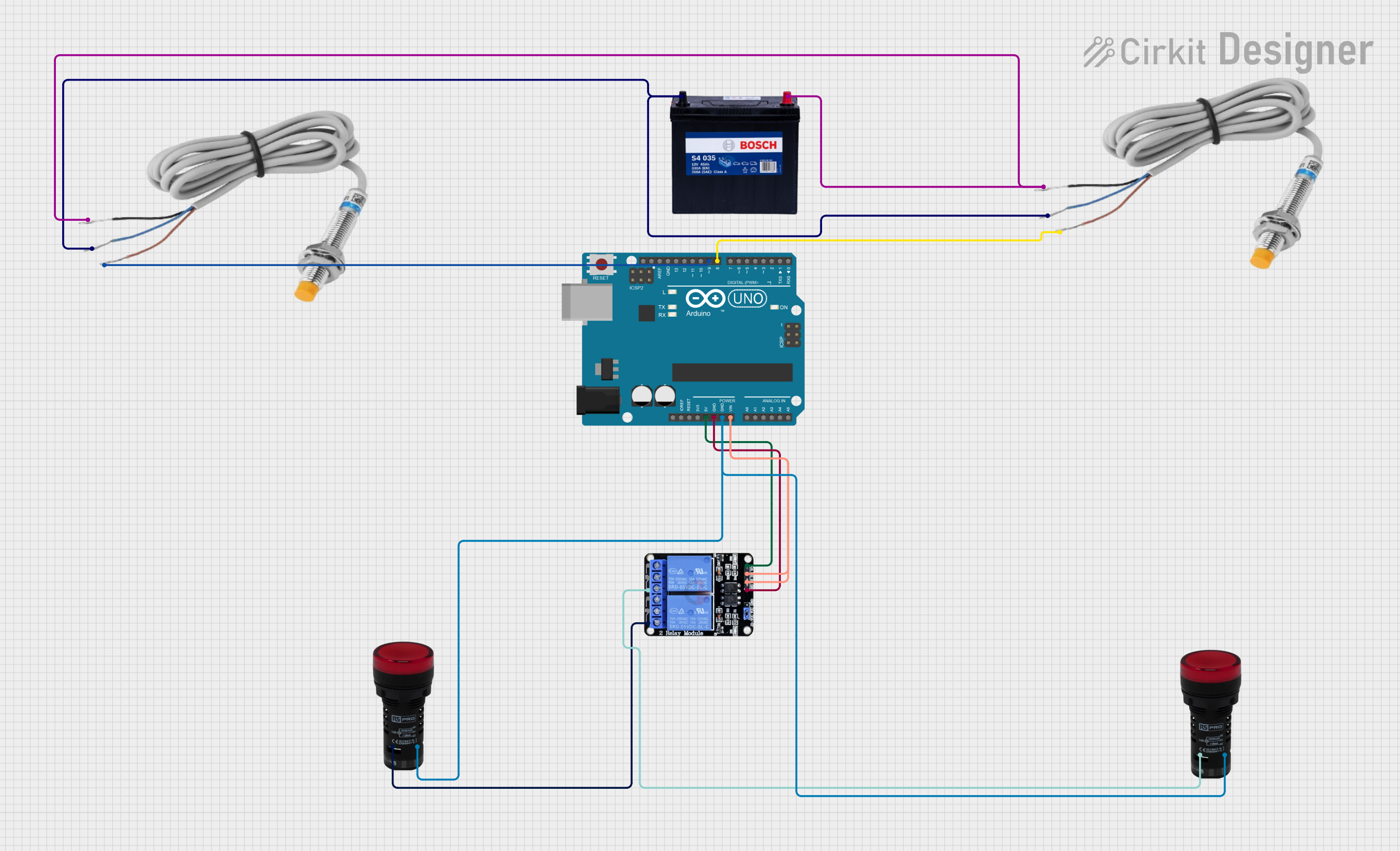
Arduino-Controlled Inductive Sensor System with Relay-Activated Pilot Lamps

Circuit Documentation
Summary of the Circuit
This circuit is designed to interface an Arduino UNO microcontroller with two inductive sensors, a two-channel relay module, and two pilot lamps. The inductive sensors are powered by a 12V 200Ah battery, which also provides power to the relay module through the Arduino UNO. The Arduino UNO controls the relay module, which in turn controls the activation of the pilot lamps. The inductive sensors are connected to the digital input pins of the Arduino UNO to provide input signals based on their sensing.
Component List
Inductive Sensor
- Description: A sensor that detects metal objects without contact.
- Pins: black (power), blue (ground), red (signal).
12V 200Ah Battery
- Description: A power source for the circuit.
- Pins: GND (ground), 12V (power supply).
Pilot Lamp Red
- Description: An indicator light that illuminates when powered.
- Pins: X1 (power), X2 (ground).
Arduino UNO
- Description: A microcontroller board based on the ATmega328P.
- Pins: Various digital I/O, analog inputs, power, ground, and other control pins.
Two Channel Relay 5v
- Description: A module with two independent relay channels to control high power devices.
- Pins: VCC (power), IN1/IN2 (control inputs), GND (ground), NO1/NO2 (normally open contacts), C1/C2 (common contacts), NC1/NC2 (normally closed contacts).
Wiring Details
Inductive Sensor
- Power (black): Connected to the 12V output of the battery.
- Ground (blue): Connected to the GND of the battery.
- Signal (red): Connected to digital pins D8 and D9 on the Arduino UNO for two separate instances of the sensor.
12V 200Ah Battery
- 12V (power supply): Connected to the black wire of both inductive sensors.
- GND (ground): Connected to the blue wire of both inductive sensors.
Pilot Lamp Red
- X1 (power): Connected to the normally open (NO) contacts of the relay module.
- X2 (ground): Connected to the GND pin on the Arduino UNO.
Arduino UNO
- Digital Pins (D8, D9): Connected to the red signal wire of the inductive sensors.
- 5V: Provides power to the VCC of the relay module.
- GND: Connected to the ground of the pilot lamps and the GND of the relay module.
- Vin: Connected to the control inputs IN1 and IN2 of the relay module.
Two Channel Relay 5v
- VCC (power): Connected to the 5V output of the Arduino UNO.
- IN1/IN2 (control inputs): Connected to the Vin pin of the Arduino UNO.
- GND (ground): Connected to the GND pin of the Arduino UNO.
- NO1/NO2 (normally open contacts): Connected to the X1 pin of the pilot lamps.
Documented Code
Arduino UNO Code (sketch.ino)
void setup() {
  // put your setup code here, to run once:

}

void loop() {
  // put your main code here, to run repeatedly:

}
Additional Notes (documentation.txt)
No additional code documentation was provided.