
Wi-Fi Controlled Smart Home Automation with ESP8266 and Relay Module
View and Edit Project In Cirkit Designer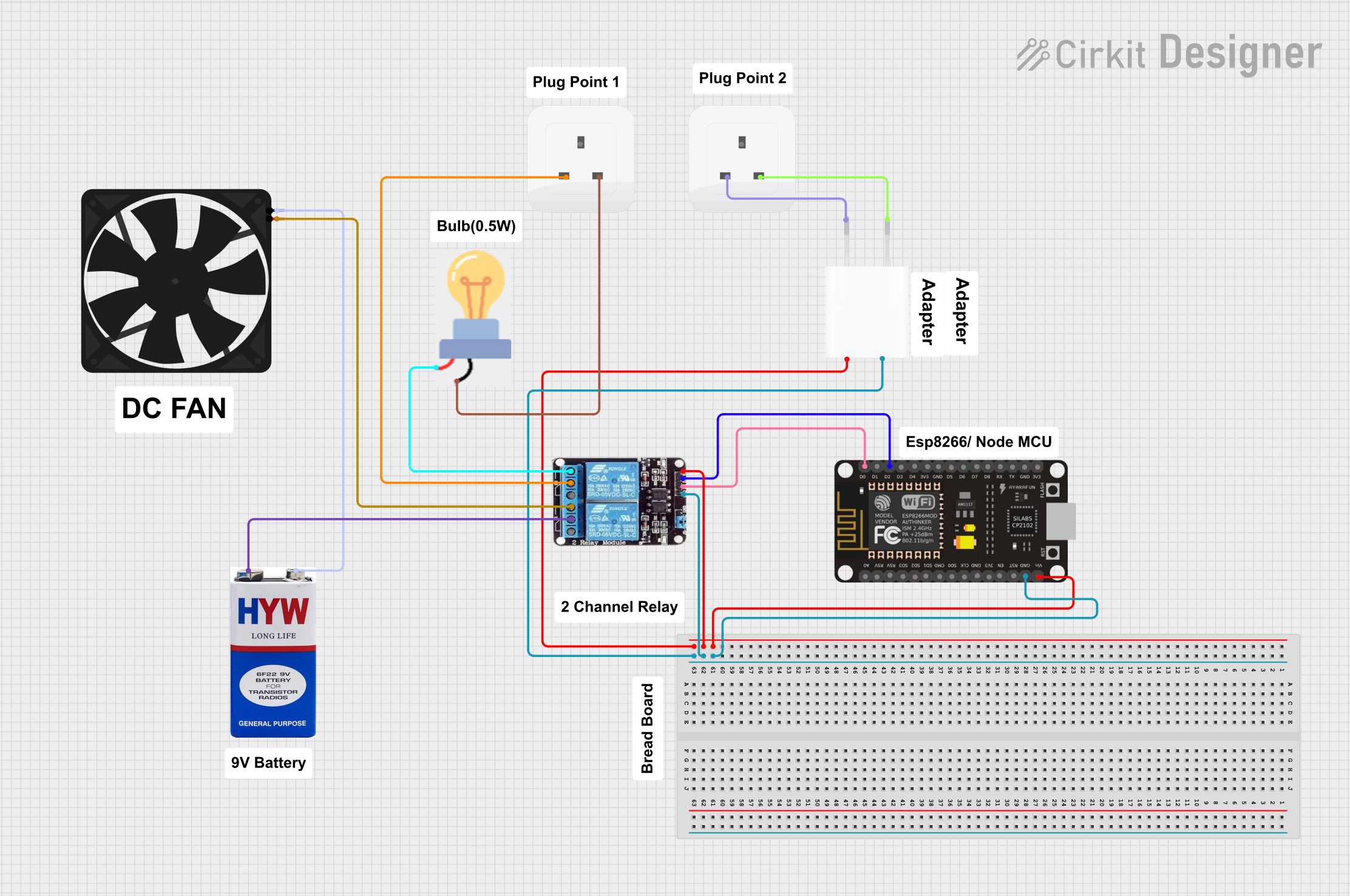
Circuit Documentation
Summary
This circuit is designed to control a fan and a bulb using an ESP8266 NodeMCU microcontroller and a 2-channel relay module. The ESP8266 is connected to a WiFi network and can be controlled remotely via the SinricPro platform. The circuit also includes a 5V adapter to power the ESP8266 and the relay module, a 9V battery to power the fan, and a socket to power the bulb.
Component List
ESP8266 NodeMCU
- Description: A low-cost Wi-Fi microchip with full TCP/IP stack and microcontroller capability.
- Pins: D0, D1, D2, D3, D4, 3V3, GND, D5, D6, D7, D8, RX, TX, A0, RSV, SD3, SD2, SD1, CMD, SD0, CLK, EN, RST, VIN
2-Channel Relay
- Description: A relay module with two channels, used to control high voltage devices.
- Pins: NC, COM, NO, VCC, IN2, IN1, GND
5V Adapter
- Description: A power adapter that converts AC to 5V DC.
- Pins: AC In 1, AC In 2, 5V, GND
Bulb
- Description: A standard light bulb.
- Pins: GND, power
Socket
- Description: A standard electrical socket.
- Pins: earth, life, neutral
Fan
- Description: A 5V DC fan.
- Pins: GND, 5V
9V Battery
- Description: A standard 9V battery.
- Pins: +, -
Wiring Details
ESP8266 NodeMCU
- VIN: Connected to VCC of the 2-Channel Relay and 5V of the 5V Adapter.
- GND: Connected to GND of the 2-Channel Relay and GND of the 5V Adapter.
- D0: Connected to IN1 of the 2-Channel Relay.
- D2: Connected to IN2 of the 2-Channel Relay.
2-Channel Relay
- VCC: Connected to VIN of the ESP8266 NodeMCU and 5V of the 5V Adapter.
- GND: Connected to GND of the ESP8266 NodeMCU and GND of the 5V Adapter.
- IN1: Connected to D0 of the ESP8266 NodeMCU.
- IN2: Connected to D2 of the ESP8266 NodeMCU.
- COM: Connected to + of the 9V Battery and life of the Socket.
- NO: Connected to 5V of the Fan and power of the Bulb.
5V Adapter
- 5V: Connected to VIN of the ESP8266 NodeMCU and VCC of the 2-Channel Relay.
- GND: Connected to GND of the ESP8266 NodeMCU and GND of the 2-Channel Relay.
- AC In 1: Connected to life of the Socket.
- AC In 2: Connected to neutral of the Socket.
Bulb
- GND: Connected to neutral of the Socket.
- power: Connected to NO of the 2-Channel Relay.
Socket
- life: Connected to COM of the 2-Channel Relay and AC In 1 of the 5V Adapter.
- neutral: Connected to AC In 2 of the 5V Adapter and GND of the Bulb.
Fan
- GND: Connected to - of the 9V Battery.
- 5V: Connected to NO of the 2-Channel Relay.
9V Battery
- +: Connected to COM of the 2-Channel Relay.
- -: Connected to GND of the Fan.
Code Documentation
Sketch (sketch.ino)
// Uncomment the following line to enable serial debug output
//#define ENABLE_DEBUG

#ifdef ENABLE_DEBUG
       #define DEBUG_ESP_PORT Serial
       #define NODEBUG_WEBSOCKETS
       #define NDEBUG
#endif

#include <Arduino.h>
#include <ESP8266WiFi.h>
#include "SinricPro.h"
#include "SinricProSwitch.h"

#include <map>

#define WIFI_SSID         "Hanuman-jio"
#define WIFI_PASS         "Madcry400"
#define APP_KEY           "188e94f1-830d-49e0-a81b-e67ac28b3c02"      // Should look like "de0bxxxx-1x3x-4x3x-ax2x-5dabxxxxxxxx"
#define APP_SECRET        "83441171-a795-4a2a-98b6-6145784a460d-cc3e80bc-0092-4c07-8712-a3dd9f1328b4"   // Should look like "5f36xxxx-x3x7-4x3x-xexe-e86724a9xxxx-4c4axxxx-3x3x-x5xe-x9x3-333d65xxxxxx"

//Enter the device IDs here
#define device_ID_1   "674091d18916d6b80a1f32bb"
#define device_ID_2   "6740a3e3716c0bcb0881b9d8"
#define device_ID_3   "6742c99e13f98f1416f3f796"
#define device_ID_4   "xxxxxxxxxxxxxxxxxxxxxxxx"

// define the GPIO connected with Relays and switches
#define RelayPin1 5  //D1
#define RelayPin2 4  //D2
#define RelayPin3 14 //D5
#define RelayPin4 12 //D6

#define SwitchPin1 10  //SD3
#define SwitchPin2 0   //D3
#define SwitchPin3 13  //D7
#define SwitchPin4 3   //RX

#define wifiLed   16   //D0

// comment the following line if you use a toggle switches instead of tactile buttons
//#define TACTILE_BUTTON 1

#define BAUD_RATE   9600

#define DEBOUNCE_TIME 250

typedef struct {      // struct for the std::map below
  int relayPIN;
  int flipSwitchPIN;
} deviceConfig_t;


// this is the main configuration
// please put in your deviceId, the PIN for Relay and PIN for flipSwitch
// this can be up to N devices...depending on how much pin's available on your device ;)
// right now we have 4 devicesIds going to 4 relays and 4 flip switches to switch the relay manually
std::map<String, deviceConfig_t> devices = {
    //{deviceId, {relayPIN,  flipSwitchPIN}}
    {device_ID_1, {  RelayPin1, SwitchPin1 }},
    {device_ID_2, {  RelayPin2, SwitchPin2 }},
    {device_ID_3, {  RelayPin3, SwitchPin3 }},
    {device_ID_4, {  RelayPin4, SwitchPin4 }}
};

typedef struct {      // struct for the std::map below
  String deviceId;
  bool lastFlipSwitchState;
  unsigned long lastFlipSwitchChange;
} flipSwitchConfig_t;

std::map<int, flipSwitchConfig_t> flipSwitches;    // this map is used to map flipSwitch PINs to deviceId and handling debounce and last flipSwitch state checks
                                                  // it will be setup in "setupFlipSwitches" function, using informations from devices map

void setupRelays() {
  for (auto &device : devices) {           // for each device (relay, flipSwitch combination)
    int relayPIN = device.second.relayPIN; // get the relay pin
    pinMode(relayPIN, OUTPUT);             // set relay pin to OUTPUT
    digitalWrite(relayPIN, HIGH);
  }
}

void setupFlipSwitches() {
  for (auto &device : devices)  {                     // for each device (relay / flipSwitch combination)
    flipSwitchConfig_t flipSwitchConfig;              // create a new flipSwitch configuration

    flipSwitchConfig.deviceId = device.first;         // set the deviceId
    flipSwitchConfig.lastFlipSwitchChange = 0;        // set debounce time
    flipSwitchConfig.lastFlipSwitchState = true;     // set lastFlipSwitchState to false (LOW)--

    int flipSwitchPIN = device.second.flipSwitchPIN;  // get the flipSwitchPIN

    flipSwitches[flipSwitchPIN] = flipSwitchConfig;   // save the flipSwitch config to flipSwitches map
    pinMode(flipSwitchPIN, INPUT_PULLUP);                   // set the flipSwitch pin to INPUT
  }
}

bool onPowerState(String deviceId, bool &state)
{
  Serial.printf("%s: %s\r\n", deviceId.c_str(), state ? "on" : "off");
  int relayPIN = devices[deviceId