Cirkit Designer
Your all-in-one circuit design IDE
Home /
Project Documentation
Arduino Nano-Based RF Receiver with Piezo Buzzer Alert
Circuit Documentation
Summary of the Circuit
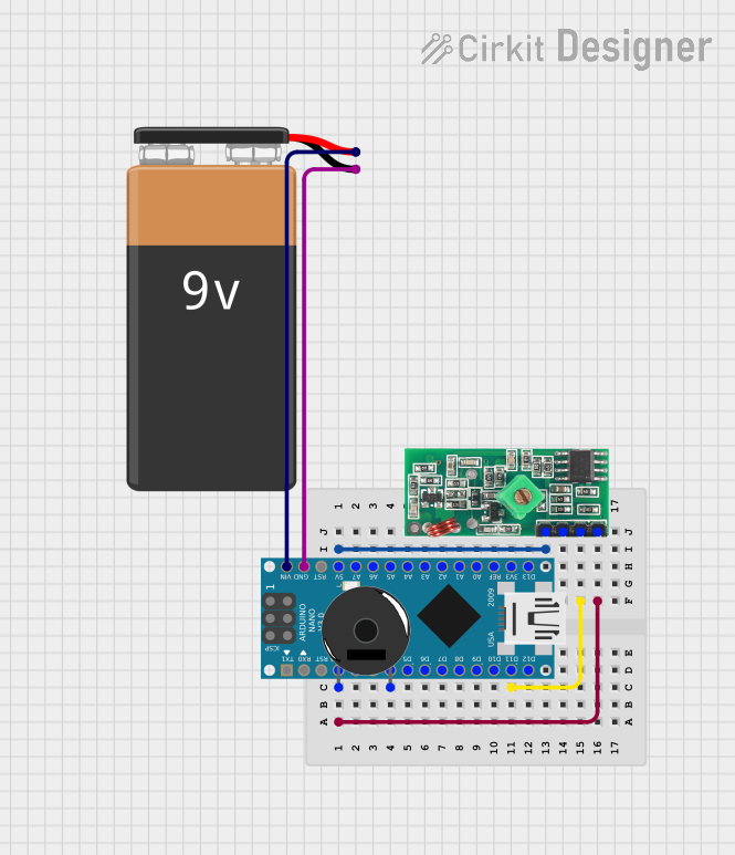
This circuit integrates an Arduino Nano microcontroller with a 433 MHz RF Receiver Module and a Piezo Buzzer, powered by a 9V battery. The Arduino Nano serves as the central processing unit, interfacing with the RF receiver to receive signals and control the Piezo Buzzer based on the received data. The 9V battery provides the necessary power to the Arduino, which regulates the voltage for its operation and supplies power to the RF receiver module.
Component List
Arduino Nano
- Description: A compact microcontroller board based on the ATmega328P.
- Pins: D1/TX, D0/RX, RESET, GND, D2, D3, D4, D5, D6, D7, D8, D9, D10, D11/MOSI, D12/MISO, VIN, 5V, A7, A6, A5, A4, A3, A2, A1, A0, AREF, 3V3, D13/SCK.
9V Battery
- Description: A standard 9V battery used to provide power to the circuit.
- Pins: -, +.
433 MHz RF Receiver Module
- Description: A radio frequency receiver module that operates at 433 MHz.
- Pins: VCC, DATA, GND.
Piezo Buzzer
- Description: An electronic device that emits sound when an electrical signal is applied.
- Pins: pin 1, pin 2.
Wiring Details
Arduino Nano
- GND: Connected to the GND of the Piezo Buzzer and 433 MHz RF Receiver Module, and the negative terminal of the 9V Battery.
- 5V: Supplies power to the VCC of the 433 MHz RF Receiver Module.
- D11/MOSI: Sends data to the DATA pin of the 433 MHz RF Receiver Module.
- VIN: Receives power from the positive terminal of the 9V Battery.
- D4: Connected to pin 2 of the Piezo Buzzer.
9V Battery
- +: Connected to the VIN of the Arduino Nano.
- -: Connected to the GND of the Arduino Nano.
433 MHz RF Receiver Module
- VCC: Powered by the 5V output from the Arduino Nano.
- DATA: Receives data from the D11/MOSI of the Arduino Nano.
- GND: Common ground with the Arduino Nano.
Piezo Buzzer
- pin 1: Connected to the GND of the Arduino Nano.
- pin 2: Controlled by the D4 pin of the Arduino Nano.
Documented Code
Arduino Nano Code (sketch.ino)
void setup() {
  // put your setup code here, to run once:

}

void loop() {
  // put your main code here, to run repeatedly:

}
Additional Notes (documentation.txt)
No additional code documentation was provided.