
ESP32-Based Ultrasonic Distance Measurement with Servo Control and Alert System
View and Edit Project In Cirkit Designer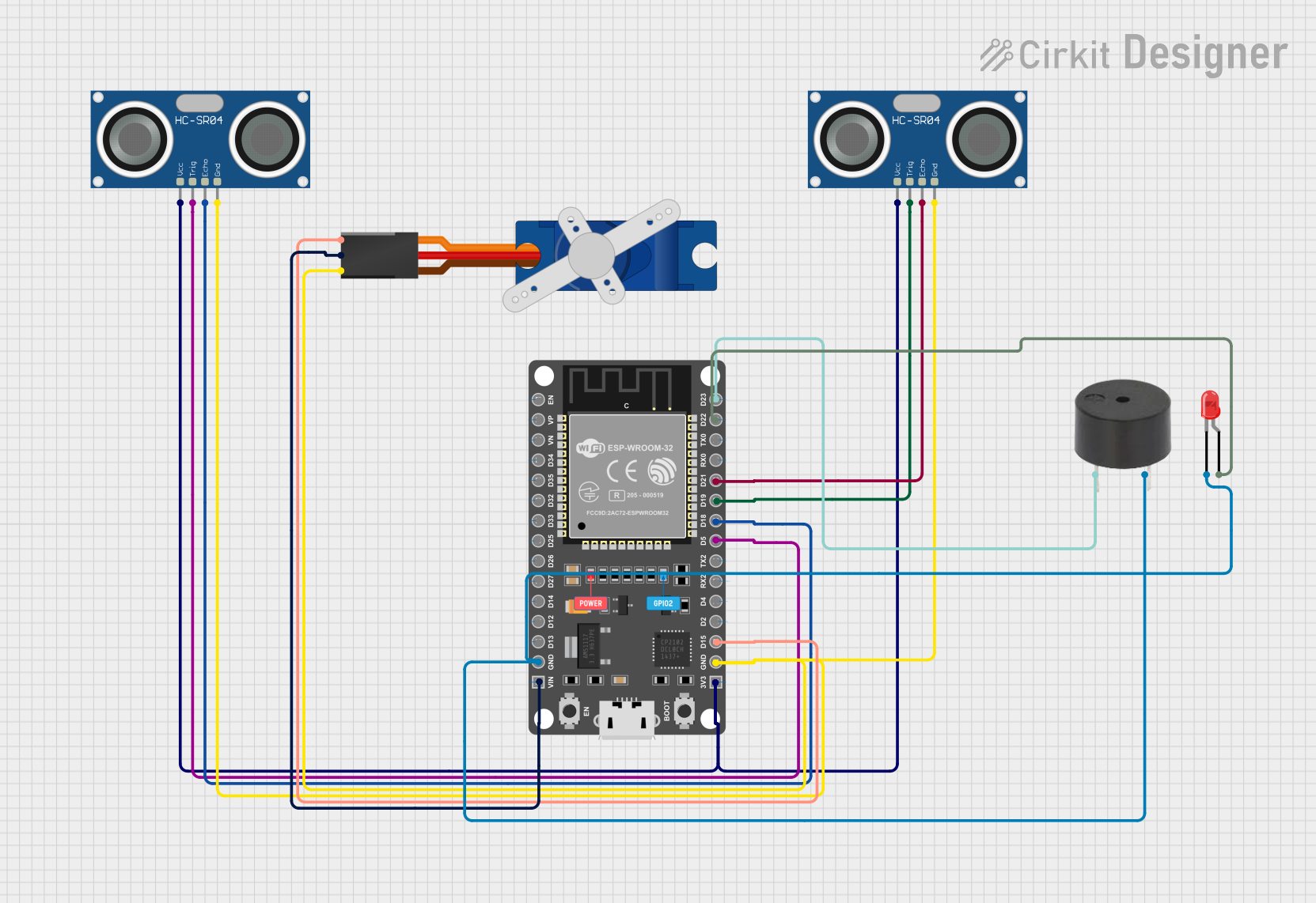
Circuit Documentation
Summary
This circuit integrates an ESP32 microcontroller with a variety of peripherals including two HC-SR04 ultrasonic sensors, a Tower Pro SG90 servo motor, a buzzer, and a red LED. The ESP32 serves as the central processing unit, controlling the servo motor, reading distance measurements from the ultrasonic sensors, and providing feedback through the buzzer and LED. The circuit is designed for applications that require distance sensing, motion control, and audio-visual signaling.
Component List
ESP 32 DEVKIT V1 (30 pins)
- Description: A microcontroller development board based on the ESP32 chip, featuring Wi-Fi and Bluetooth connectivity.
- Pins: EN, VP, VN, D34, D35, D32, D33, D25, D26, D27, D14, D12, D13, GND, VIN, 3V3, D15, D2, D4, RX2, TX2, D5, D18, D19, D21, RX0, TX0, D22, D23
HC-SR04 Ultrasonic Sensor (x2)
- Description: An ultrasonic distance sensor capable of measuring distances by emitting ultrasonic waves and measuring the time taken for the echo to return.
- Pins: VCC, TRIG, ECHO, GND
Tower Pro SG90 servo
- Description: A small and lightweight servo motor suitable for a wide range of motion control applications.
- Pins: Signal, +5V, GND
Buzzer
- Description: An electronic buzzer that can produce a tone when powered.
- Pins: PIN, GND
LED: Two Pin (red)
- Description: A basic red LED for visual signaling.
- Pins: Cathode, Anode
Wiring Details
ESP 32 DEVKIT V1 (30 pins)
- GND: Connected to the GND pins of the buzzer, both HC-SR04 ultrasonic sensors, the servo motor, and the cathode of the LED.
- VIN: Connected to the +5V pin of the Tower Pro SG90 servo.
- 3V3: Connected to the VCC pins of both HC-SR04 ultrasonic sensors.
- D15: Connected to the Signal pin of the Tower Pro SG90 servo.
- D5: Connected to the TRIG pin of the first HC-SR04 ultrasonic sensor.
- D18: Connected to the ECHO pin of the first HC-SR04 ultrasonic sensor.
- D19: Connected to the TRIG pin of the second HC-SR04 ultrasonic sensor.
- D21: Connected to the ECHO pin of the second HC-SR04 ultrasonic sensor.
- D22: Connected to the anode of the LED.
- D23: Connected to the PIN of the buzzer.
HC-SR04 Ultrasonic Sensor
- VCC: Connected to the 3V3 pin of the ESP32.
- TRIG: Connected to the D5 pin of the ESP32 for the first sensor, and D19 for the second sensor.
- ECHO: Connected to the D18 pin of the ESP32 for the first sensor, and D21 for the second sensor.
- GND: Connected to the GND pin of the ESP32.
Tower Pro SG90 servo
- Signal: Connected to the D15 pin of the ESP32.
- +5V: Connected to the VIN pin of the ESP32.
- GND: Connected to the GND pin of the ESP32.
Buzzer
- PIN: Connected to the D23 pin of the ESP32.
- GND: Connected to the GND pin of the ESP32.
LED: Two Pin (red)
- Cathode: Connected to the GND pin of the ESP32.
- Anode: Connected to the D22 pin of the ESP32.
Documented Code
There is no code provided for the microcontroller. To fully utilize this circuit, embedded code needs to be written and uploaded to the ESP32 microcontroller. The code should initialize the GPIO pins, set up communication with the ultrasonic sensors, control the servo motor, and manage the buzzer and LED based on sensor inputs or other logic conditions.