
Arduino Nano Controlled Power Management System with AC-DC Conversion and Relay Switching
View and Edit Project In Cirkit Designer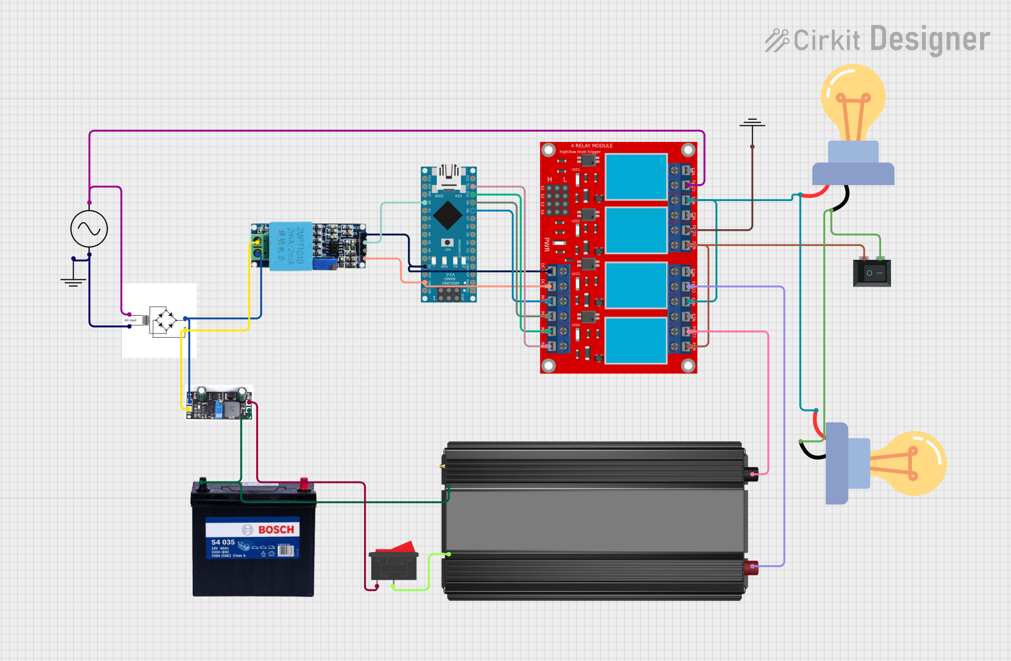
Circuit Documentation
Summary
The circuit in question appears to be a control system that utilizes an Arduino Nano as the central processing unit, interfacing with a 4-channel relay module to control various loads. The system is powered by an AC supply, which is rectified to DC using a bridge rectifier. A voltage sensor is used to monitor the voltage levels in the circuit, and a charge controller is included to manage the charging of a 12V 200Ah battery. The battery provides power to a power inverter, which in turn supplies AC power to LED bulbs. Rocker switches are used to control the flow of power to the inverter and the relay module.
Component List
- Arduino Nano: A microcontroller board based on the ATmega328P. It has a variety of digital and analog I/O pins.
- Bridge Rectifier: A device that converts an AC input into a DC output.
- AC Supply: Provides alternating current power to the circuit.
- 12V 200Ah Battery: A high-capacity battery that stores electrical energy.
- Power Inverter: Converts DC power from the battery into AC power.
- Charge Controller: Manages the charging process for the battery to prevent overcharging.
- Voltage Sensor: Measures the voltage in the circuit and provides feedback to the Arduino.
- 4 Channel Relay Module: Allows the Arduino to control higher power loads.
- LED Bulb AC: An AC-powered light-emitting diode bulb.
- Ground (GND): A reference point in an electrical circuit from which voltages are measured.
- Rocker Switch: A switch that allows current to flow when in one position and breaks the circuit when in the other.
- Rocker Switch (SPST): A single-pole single-throw switch that controls a circuit.
Wiring Details
Arduino Nano
- Digital Pin 8 (D8) connected to Relay Module IN 1
- Digital Pin 9 (D9) connected to Relay Module IN 2
- Digital Pin 10 (D10) connected to Relay Module IN 3
- Digital Pin 11 (D11/MOSI) connected to Relay Module IN 4
- Ground (GND) connected to Voltage Sensor Ground and Relay Module VCC- (GND)
- 5V output connected to Voltage Sensor Vcc and Relay Module VCC+
- Analog Pin 0 (A0) connected to Voltage Sensor Out
Bridge Rectifier
- AC input + connected to AC Supply +ve
- AC input - connected to AC Supply -ve
- DC output + connected to Voltage Sensor Phase and Charge Controller Vin
- DC output - connected to Voltage Sensor Ground and Charge Controller GND
AC Supply
- +ve connected to Bridge Rectifier AC input +
- -ve connected to Bridge Rectifier AC input -
12V 200Ah Battery
- GND connected to Power Inverter - and Charge Controller GND
- 12V connected to Rocker Switch 1 and Charge Controller BAT
Power Inverter
-
- connected to Battery GND and Relay Module COM 4
-
- connected to Battery 12V via Rocker Switch 2 and Relay Module COM 3
Charge Controller
- GND connected to Bridge Rectifier - and Battery GND
- BAT connected to Battery 12V
- Vin connected to Bridge Rectifier +
Voltage Sensor
- Ground connected to Bridge Rectifier -
- Phase connected to Bridge Rectifier +
- Vcc connected to Arduino Nano 5V
- Out connected to Arduino Nano A0
- Gnd connected to Arduino Nano GND
4 Channel Relay Module
- IN 1 to IN 4 connected to Arduino Nano D8 to D11 respectively
- VCC+ connected to Arduino Nano 5V
- VCC- (GND) connected to Arduino Nano GND
- COM 1 connected to AC Supply +ve
- COM 2 connected to GND
- COM 3 connected to Power Inverter +
- COM 4 connected to Power Inverter -
- N.O. 1 and N.O. 3 connected to LED Bulb AC +
- N.O. 2 and N.O. 4 connected to Rocker Switch (SPST) 1
LED Bulb AC
-
- connected to Relay Module N.O. 1 and N.O. 3
-
- connected to Rocker Switch (SPST) 2
Rocker Switch
- 1 connected to Battery 12V
- 2 connected to Power Inverter +
Rocker Switch (SPST)
- 1 connected to Relay Module N.O. 2 and N.O. 4
- 2 connected to LED Bulb AC -
Documented Code
Arduino Nano Code (sketch.ino)
void setup() {
  // put your setup code here, to run once:

}

void loop() {
  // put your main code here, to run repeatedly:

}
Note: The provided code is a template and does not contain any functional code to control the relay module or read from the voltage sensor. This will need to be implemented based on the specific requirements of the circuit.