Cirkit Designer
Your all-in-one circuit design IDE
Home /
Project Documentation
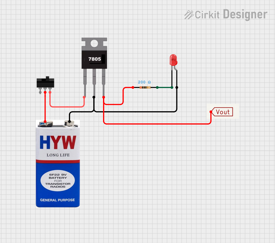
Battery-Powered LED Indicator with 7805 Voltage Regulator
Circuit Documentation
Summary
This circuit is a simple power regulation and LED indicator circuit. It uses a 9V battery as the power source, a 7805 voltage regulator to step down the voltage to 5V, a toggle switch to control the power, and an LED with a current-limiting resistor to indicate the power status.
Component List
7805 Voltage Regulator
- Pins: Vin, Gnd, Vout
- Description: A voltage regulator that steps down the input voltage to a stable 5V output.
- Purpose: To provide a stable 5V output from a 9V battery.
9V Battery
- Pins: +, -
- Description: A 9V battery used as the power source for the circuit.
- Purpose: To supply power to the circuit.
Toggle Switch
- Pins: L1, COM, L2
- Description: A switch used to control the power flow in the circuit.
- Purpose: To turn the circuit on and off.
LED: Two Pin (red)
- Pins: cathode, anode
- Description: A red LED used as an indicator.
- Purpose: To indicate the power status of the circuit.
Resistor
- Pins: pin1, pin2
- Description: A resistor with a resistance of 200 Ohms.
- Purpose: To limit the current flowing through the LED.
Vout
- Pins: Vout
- Description: A terminal to access the regulated 5V output.
- Purpose: To provide a connection point for the 5V output.
Wiring Details
7805 Voltage Regulator
- Vin: Connected to L2 of the Toggle Switch.
- Gnd: Connected to the anode of the LED and the negative terminal of the 9V battery.
- Vout: Connected to Vout terminal and pin1 of the Resistor.
9V Battery
- +: Connected to COM of the Toggle Switch.
- -: Connected to the anode of the LED and Gnd of the 7805 Voltage Regulator.
Toggle Switch
- L1: Not connected.
- COM: Connected to the positive terminal of the 9V battery.
- L2: Connected to Vin of the 7805 Voltage Regulator.
LED: Two Pin (red)
- cathode: Connected to pin2 of the Resistor.
- anode: Connected to Gnd of the 7805 Voltage Regulator and the negative terminal of the 9V battery.
Resistor
- pin1: Connected to Vout of the 7805 Voltage Regulator.
- pin2: Connected to the cathode of the LED.
Vout
- Vout: Connected to Vout of the 7805 Voltage Regulator and pin1 of the Resistor.
Code
There is no microcontroller code associated with this circuit.