Cirkit Designer
Your all-in-one circuit design IDE
Home /
Project Documentation
Arduino UNO LED Blinker with Resistor
Circuit Documentation
Summary
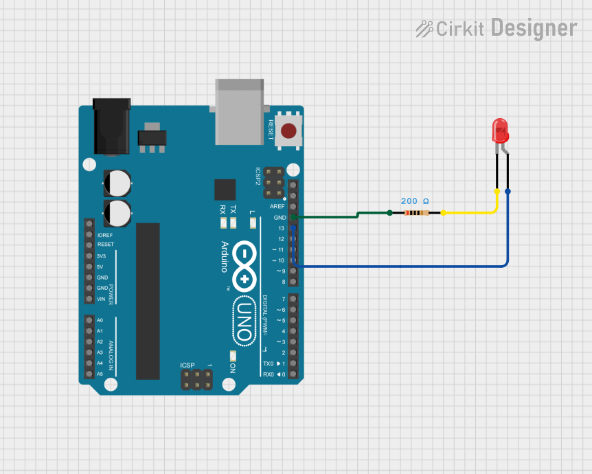
This circuit consists of an Arduino UNO microcontroller, a red LED, and a 200 Ohm resistor. The Arduino UNO is programmed to blink the LED on and off at one-second intervals.
Component List
LED: Two Pin (red)
- Description: A red LED with two pins: anode and cathode.
- Purpose: To emit light when current flows through it.
Resistor
- Description: A resistor with two pins.
- Purpose: To limit the current flowing through the LED.
- Properties:
- Resistance: 200 Ohms
Arduino UNO
- Description: A microcontroller board based on the ATmega328P.
- Purpose: To control the LED blinking through its digital I/O pins.
- Pins:
- UNUSED
- IOREF
- Reset
- 3.3V
- 5V
- GND
- Vin
- A0
- A1
- A2
- A3
- A4
- A5
- SCL
- SDA
- AREF
- D13
- D12
- D11
- D10
- D9
- D8
- D7
- D6
- D5
- D4
- D3
- D2
- D1
- D0
Wiring Details
LED: Two Pin (red)
- Anode: Connected to D13 of the Arduino UNO.
- Cathode: Connected to pin2 of the Resistor.
Resistor
- Pin1: Connected to GND of the Arduino UNO.
- Pin2: Connected to the cathode of the LED.
Arduino UNO
- D13: Connected to the anode of the LED.
- GND: Connected to pin1 of the Resistor.
Code Documentation
Arduino UNO Code
void setup() {
  // put your setup code here, to run once:
  pinMode(13, OUTPUT);
}

void loop() {
  // put your main code here, to run repeatedly:
  digitalWrite(13, HIGH);
  delay(1000);
  digitalWrite(13, LOW);
  delay(1000);
}
This code sets up pin 13 of the Arduino UNO as an output pin. In the main loop, it turns the LED on for one second and then off for one second, creating a blinking effect.