
Circuit Documentation
Summary
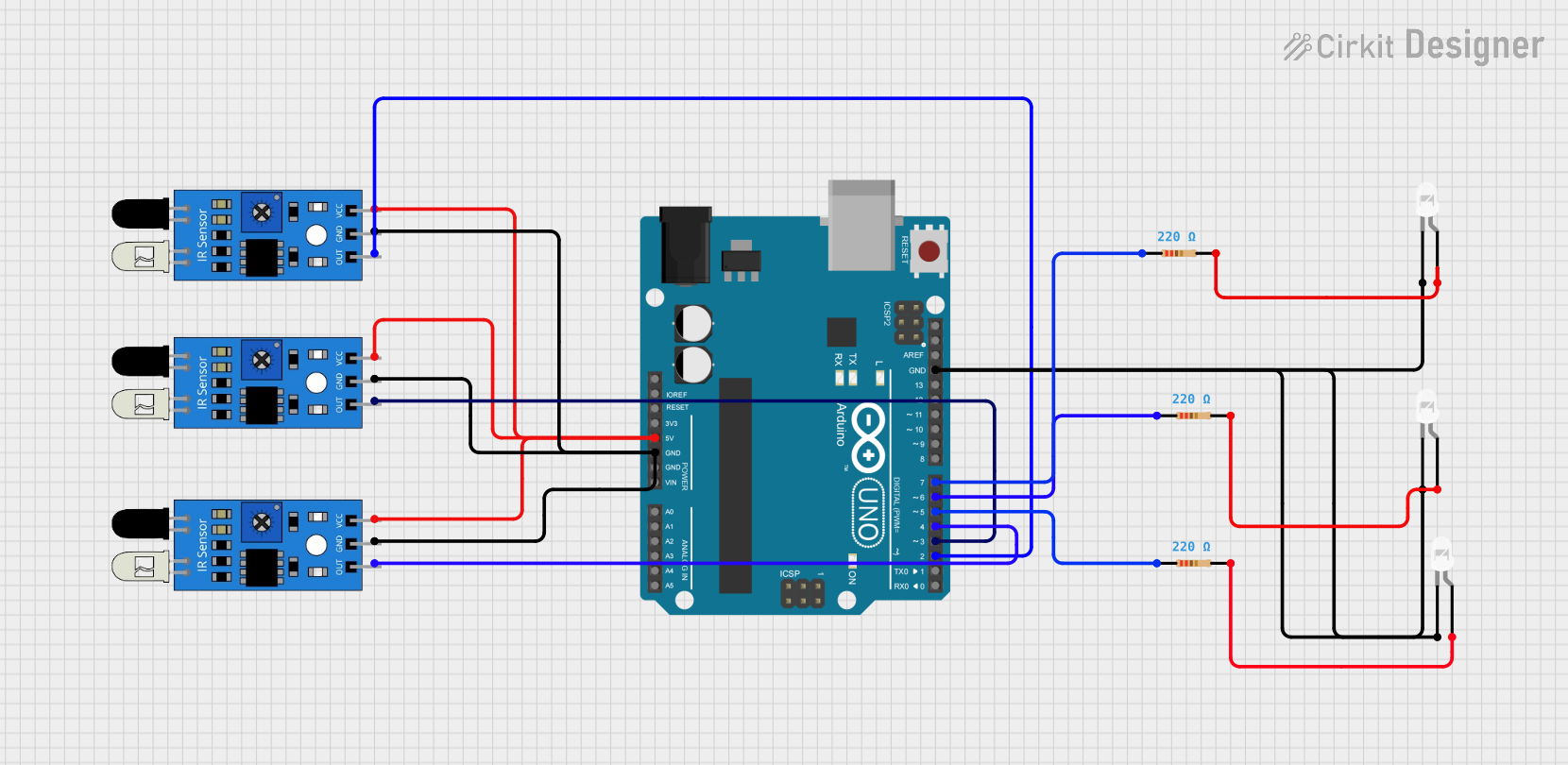
The circuit consists of an Arduino UNO microcontroller interfaced with three infrared (IR) sensors and three LEDs, each with a corresponding resistor. The IR sensors are powered by the 5V output from the Arduino and are grounded to the Arduino's GND pin. The output of each IR sensor is connected to a digital input pin on the Arduino. Each LED is connected in series with a 220-ohm resistor, and the cathodes of the LEDs are connected to the Arduino's GND. The anodes of the LEDs are driven by digital output pins on the Arduino through the resistors. The Arduino is programmed to read the state of the IR sensors and control the LEDs accordingly.
Component List
Arduino UNO
- Description: A microcontroller board based on the ATmega328P.
- Pins: UNUSED, IOREF, Reset, 3.3V, 5V, GND, Vin, A0-A5, SCL, SDA, AREF, D13-D0
IR Sensor
- Description: An infrared sensor for detecting proximity or measuring intensity of IR light.
- Pins: out, gnd, vcc
Resistor (220 Ohms)
- Description: A resistor with a resistance of 220 ohms.
- Pins: pin1, pin2
LED: Two Pin (white)
- Description: A white light-emitting diode.
- Pins: cathode, anode
Wiring Details
Arduino UNO
- 5V: Connected to the VCC of all IR sensors.
- GND: Connected to the GND of all IR sensors and the cathodes of all LEDs.
- D7, D6, D5: Connected to the pin1 of each resistor.
- D4, D3, D2: Connected to the 'out' pin of each IR sensor.
IR Sensor
- VCC: Connected to the 5V of Arduino UNO.
- GND: Connected to the GND of Arduino UNO.
- OUT: Connected to digital input pins D4, D3, D2 on the Arduino UNO.
Resistor (220 Ohms)
- Pin1: Connected to digital output pins D7, D6, D5 on the Arduino UNO.
- Pin2: Connected to the anode of each LED.
LED: Two Pin (white)
- Cathode: Connected to the GND of Arduino UNO.
- Anode: Connected to pin2 of each resistor.
Documented Code
// Define pin numbers
const int INPUT1_PIN = 2;
const int INPUT2_PIN = 3;
const int INPUT3_PIN = 4;
const int OUTPUT1_PIN = 5;
const int OUTPUT2_PIN = 6;
const int OUTPUT3_PIN = 7;

void setup() {
  pinMode(INPUT1_PIN, INPUT);
  pinMode(INPUT2_PIN, INPUT);
  pinMode(INPUT3_PIN, INPUT);
  pinMode(OUTPUT1_PIN, OUTPUT);
  pinMode(OUTPUT2_PIN, OUTPUT);
  pinMode(OUTPUT3_PIN, OUTPUT);
}

void loop() {
  int input1 = digitalRead(INPUT1_PIN);
  int input2 = digitalRead(INPUT2_PIN);
  int input3 = digitalRead(INPUT3_PIN);

  // Check the combination of inputs and set the outputs accordingly
  if (input1 == HIGH && input2 == HIGH && input3 == HIGH) {
    digitalWrite(OUTPUT1_PIN, HIGH);
    digitalWrite(OUTPUT2_PIN, HIGH);
    digitalWrite(OUTPUT3_PIN, HIGH);
  } else if (input1 == HIGH && input2 == HIGH) {
    digitalWrite(OUTPUT1_PIN, HIGH);
    digitalWrite(OUTPUT2_PIN, HIGH);
    digitalWrite(OUTPUT3_PIN, LOW);
  } else if (input2 == HIGH && input3 == HIGH) {
    digitalWrite(OUTPUT1_PIN, LOW);
    digitalWrite(OUTPUT2_PIN, HIGH);
    digitalWrite(OUTPUT3_PIN, HIGH);
  } else if (input1 == HIGH && input3 == HIGH) {
    digitalWrite(OUTPUT1_PIN, HIGH);
    digitalWrite(OUTPUT2_PIN, LOW);
    digitalWrite(OUTPUT3_PIN, HIGH);
  } else if (input1 == HIGH) {
    digitalWrite(OUTPUT1_PIN, HIGH);
    digitalWrite(OUTPUT2_PIN, LOW);
    digitalWrite(OUTPUT3_PIN, LOW);
  } else if (input2 == HIGH) {
    digitalWrite(OUTPUT1_PIN, LOW);
    digitalWrite(OUTPUT2_PIN, HIGH);
    digitalWrite(OUTPUT3_PIN, LOW);
  } else if (input3 == HIGH) {
    digitalWrite(OUTPUT1_PIN, LOW);
    digitalWrite(OUTPUT2_PIN, LOW);
    digitalWrite(OUTPUT3_PIN, HIGH);
  } else {
    // If all inputs are LOW, turn off all outputs
    digitalWrite(OUTPUT1_PIN, LOW);
    digitalWrite(OUTPUT2_PIN, LOW);
    digitalWrite(OUTPUT3_PIN, LOW);
  }
}
This code is designed to read the state of three IR sensors connected to digital input pins D2, D3, and D4. Depending on the combination of high (detected) and low (not detected) signals from the sensors, the code controls three LEDs connected to digital output pins D5, D6, and D7. The LEDs are turned on or off to reflect the state of the IR sensors.