ESP32-Controlled Robotic Vehicle with Ultrasonic Distance Sensing and Motor Encoder Feedback
Circuit Documentation
Summary
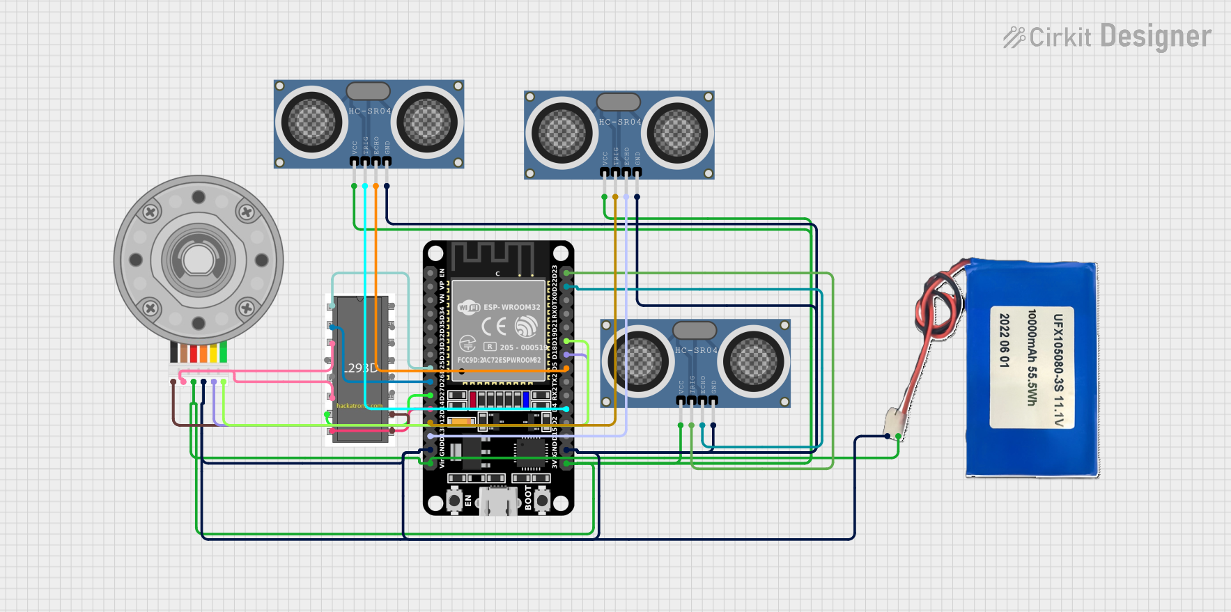
The circuit in question is designed to control a DC motor with an encoder using an ESP32 microcontroller and a motor driver. It also includes three HC-SR04 ultrasonic distance sensors for distance measurement. The system is powered by a Lithium-ion battery. The ESP32 microcontroller interfaces with the motor driver to control the motor's speed and direction, reads the encoder signals to determine the motor's position, and triggers the ultrasonic sensors to measure distances.
Component List
ESP32 (30 pin)
- Microcontroller with WiFi and Bluetooth capabilities.
- It has a variety of digital I/O pins and power pins.
Motor Driver
- An electronic module that drives the DC motor.
- It has multiple input and output pins for controlling one or more motors.
HC-SR04 Ultrasonic Distance Sensor (Wokwi Compatible)
- A sensor that measures distance using ultrasonic waves.
- It has four pins: VCC, TRIG, ECHO, and GND.
DC Motor with Encoder
- A motor that provides rotational movement with feedback from an encoder.
- It has six pins: Encoder B, Encoder A, GND, VCC, Motor +ve, and Motor -ve.
Lithium-ion Battery 10000mah
- A rechargeable power source.
- It has two pins: 11.1V and GND.
Wiring Details
ESP32 (30 pin)
- D25 connected to Motor Driver pin 1
- D26 connected to Motor Driver pin 2
- D27 connected to Motor Driver pin 7
- D14 connected to Motor Driver pin 8
- D12 connected to HC-SR04 Ultrasonic Sensor TRIG
- D13 connected to HC-SR04 Ultrasonic Sensor ECHO
- GND connected to common ground net
- Vin connected to Lithium-ion Battery 11.1V
- 3V3 connected to HC-SR04 Ultrasonic Sensor VCC
- D23 connected to HC-SR04 Ultrasonic Sensor TRIG
- D22 connected to HC-SR04 Ultrasonic Sensor ECHO
- D19 connected to DC Motor Encoder B
- D18 connected to DC Motor Encoder A
- D5 connected to HC-SR04 Ultrasonic Sensor ECHO
- D4 connected to HC-SR04 Ultrasonic Sensor TRIG
Motor Driver
- pin 1 connected to ESP32 D25
- pin 2 connected to ESP32 D26
- pin 7 connected to ESP32 D27
- pin 8 connected to ESP32 D14
- pin 3 and pin 6 connected to DC Motor Motor +ve
- pin 9 and pin 10 connected to DC Motor Motor -ve
HC-SR04 Ultrasonic Distance Sensor (Wokwi Compatible)
- TRIG connected to ESP32 D12, D23, D4 (for different instances)
- ECHO connected to ESP32 D13, D22, D5 (for different instances)
- GND connected to common ground net
- VCC connected to ESP32 3V3
DC Motor with Encoder
- Encoder B connected to ESP32 D19
- Encoder A connected to ESP32 D18
- GND connected to common ground net
- VCC connected to Lithium-ion Battery 11.1V
- Motor +ve connected to Motor Driver pin 3 and pin 6
- Motor -ve connected to Motor Driver pin 9 and pin 10
Lithium-ion Battery 10000mah
- 11.1V connected to ESP32 Vin and DC Motor VCC
- GND connected to common ground net
Documented Code
// Code for ESP32 (30 pin)
void setup() {
  // Define pin modes for the ultrasonic sensors
  pinMode(TRIG_PIN, OUTPUT);
  pinMode(ECHO_PIN, INPUT);
  // Define pin modes for the motor driver
  pinMode(MOTOR_DRIVER_PIN1, OUTPUT);
  pinMode(MOTOR_DRIVER_PIN2, OUTPUT);
  pinMode(MOTOR_DRIVER_PIN7, OUTPUT);
  pinMode(MOTOR_DRIVER_PIN8, OUTPUT);
  // Define pin modes for the encoder
  pinMode(ENCODER_A_PIN, INPUT);
  pinMode(ENCODER_B_PIN, INPUT);
}

void loop() {
  // Main code to control the motor and read sensors
}
This code snippet is a basic setup for the ESP32 microcontroller. It defines the pin modes for the ultrasonic sensors, motor driver, and encoder. The loop function is left empty as the implementation details for controlling the motor and reading from the sensors are not provided.