
Circuit Documentation
Summary
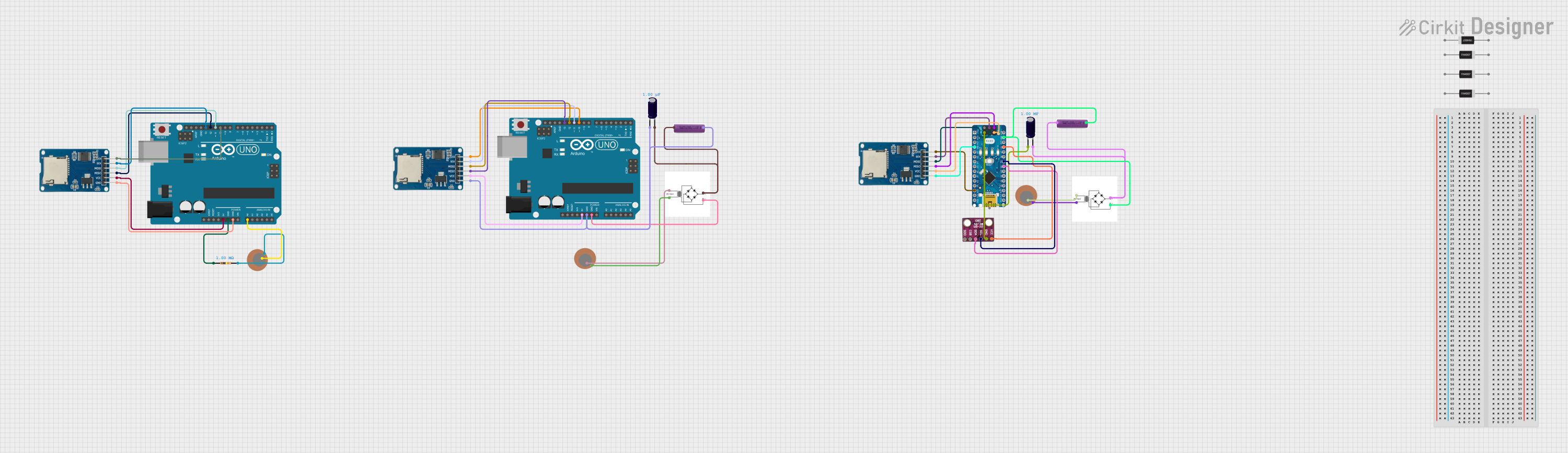
This circuit is designed to capture voltage readings from piezo sensors and store the data on an SD card using Arduino microcontrollers. The circuit includes two Arduino UNOs and one Arduino Nano, each interfaced with a Micro SD Card Module for data logging. Piezo sensors are connected to the Arduinos to detect vibrations and convert them into electrical signals. The circuit also features bridge rectifiers to convert AC signals from the piezo sensors to DC, electrolytic capacitors for voltage smoothing, and resistors for current limiting. The system is powered by 3.7V batteries.
Component List
Microcontrollers
- Arduino UNO: A microcontroller board based on the ATmega328P, featuring digital and analog I/O pins.
- Arduino Nano: A small, complete, and breadboard-friendly board based on the ATmega328P, similar to the Arduino UNO.
Sensors
- Piezo Sensor: A device that converts mechanical stress into an electrical charge, used for sensing vibrations.
Storage Modules
- Micro SD Card Module: A module that allows an Arduino board to read and write data to a micro SD card.
Power Components
- 3.7V Battery: A rechargeable battery that provides power to the circuit.
- Bridge Rectifier: A component that converts an AC input into a DC output.
- Electrolytic Capacitor: A capacitor used for filtering and smoothing the DC output from the rectifier.
Passive Components
- Resistor: A component that limits the flow of electric current, used here for current limiting.
- 1N4007 Rectifier Diode: A diode that allows current to flow in only one direction, used for rectification.
Sensor Modules
- BMP280: A digital barometric pressure and temperature sensor module.
Wiring Details
Arduino UNO
- 5V connected to Micro SD Card Module VCC.
- GND connected to Resistor pin1, Micro SD Card Module GND, and Bridge Rectifier -.
- A0 connected to Piezo Sensor +.
- D13 connected to Micro SD Card Module SCK.
- D12 connected to Micro SD Card Module MISO.
- D11 connected to Micro SD Card Module MOSI.
- D10 connected to Micro SD Card Module CS.
Piezo Sensor
- + connected to Arduino UNO A0 and Bridge Rectifier AC input +.
- - connected to Resistor pin2 and Bridge Rectifier AC input -.
Micro SD Card Module
- VCC connected to Arduino UNO 5V.
- GND connected to Arduino UNO GND.
- SCK connected to Arduino UNO D13.
- MISO connected to Arduino UNO D12.
- MOSI connected to Arduino UNO D11.
- CS connected to Arduino UNO D10.
Resistor
- Pin1 connected to Arduino UNO GND.
- Pin2 connected to Piezo Sensor -.
Bridge Rectifier
- AC input + connected to Piezo Sensor +.
- AC input - connected to Piezo Sensor -.
- + connected to 3.7V Battery + and Electrolytic Capacitor +.
- - connected to Arduino UNO GND.
Electrolytic Capacitor
- + connected to 3.7V Battery + and Bridge Rectifier +.
- - connected to Arduino UNO GND.
3.7V Battery
- + connected to Bridge Rectifier + and Electrolytic Capacitor +.
- - connected to Bridge Rectifier - and Electrolytic Capacitor -.
Arduino Nano
- GND connected to Micro SD Card Module GND, BMP280 GND, and Electrolytic Capacitor -.
- 5V connected to BMP280 VCC and Micro SD Card Module VCC.
- A5 connected to BMP280 SCL.
- A4 connected to BMP280 SDA.
- D12/MISO connected to Micro SD Card Module MISO.
- D13/SCK connected to Micro SD Card Module SCK.
- D11/MOSI connected to Micro SD Card Module MOSI.
- D10 connected to Micro SD Card Module CS.
BMP280
- VCC connected to Arduino Nano 5V.
- GND connected to Arduino Nano GND.
- SCL connected to Arduino Nano A5.
- SDA connected to Arduino Nano A4.
Documented Code
Arduino UNO Code (First Instance)
#include <SPI.h>
#include <SD.h>

const int sensorPin = A0; // Analog pin connected to piezo sensor
File myFile;

void setup() {
    Serial.begin(9600);
    // Initialize SD card
    if (!SD.begin(10)) {
        Serial.println("SD card initialization failed!");
        return;
    }
    Serial.println("SD card is ready.");

    // Create/Open file
    myFile = SD.open("data.txt", FILE_WRITE);
    if (myFile) {
        myFile.println("Time (s), Voltage (V)"); // Header for data
        myFile.close(); // Close file after writing header
    } else {
        Serial.println("Error opening data.txt");
    }
}

void loop() {
    unsigned long currentTime = millis() / 1000; // Time in seconds
    int sensorValue = analogRead(sensorPin); // Read analog value from sensor
    float voltage = sensorValue * (5.0 / 1023.0); // Convert ADC value to voltage

    // Open file for writing
    myFile = SD.open("data.txt", FILE_WRITE);
    if (myFile) {
        myFile.print(currentTime); // Print time in seconds
        myFile.print(", ");
        myFile.println(voltage); // Print voltage in volts
        myFile.close(); // Close file after writing data
    } else {
        Serial.println("Error opening data.txt");
    }

    delay(100); // Delay for 100 ms (10 readings per second)
}
Arduino UNO Code (Second Instance)
void setup() {
  // put your setup code here, to run once:

}

void loop() {
  // put your main code here, to run repeatedly:

}
Arduino Nano Code
/*
 * This Arduino Sketch reads voltage data from a piezo sensor and stores it
 * on an SD card at a rate of 10 readings per second. The piezoelectricity
 * generated is stored in a connected battery.
 */

#include <SPI.h>
#include <SD.h>

const int sensorPin = A0; // Analog pin connected to piezo sensor
File myFile;

void setup() {
    Serial.begin(9600);
    // Initialize SD card
    if (!SD.begin(10)) {
        Serial.println("SD card initialization failed!");
        return;
    }
    Serial.println("SD card is ready.");

    // Create/Open file
    myFile = SD.open("data.txt", FILE_WRITE);
    if (myFile) {
        myFile.println("Time (s), Voltage (V)"); // Header for data
        myFile.close(); // Close file after writing header
    } else {
        Serial.println("Error opening data.txt");
    }
}

void loop() {
    unsigned long currentTime = millis() / 1000; // Time in seconds
    int sensorValue = analogRead(sensorPin); // Read analog value from sensor
    float voltage = sensorValue * (5.0 / 1023.0); // Convert ADC value to voltage

    // Open file for writing
    myFile = SD.open("data.txt", FILE_WRITE);
    if (myFile) {
        myFile.print(currentTime); // Print time in seconds
        myFile.print(", ");
        myFile.println(voltage); // Print voltage in volts
        myFile.close(); // Close file after writing data
    } else {
        Serial.println("Error opening data.txt");
    }

    delay(100); // Delay for 100 ms (10 readings per second)
}
This concludes the documentation for the provided circuit design and embedded code.