
ESP32-Based Wi-Fi Controlled Water Management System with Flow Sensors and Solenoid Valves
View and Edit Project In Cirkit Designer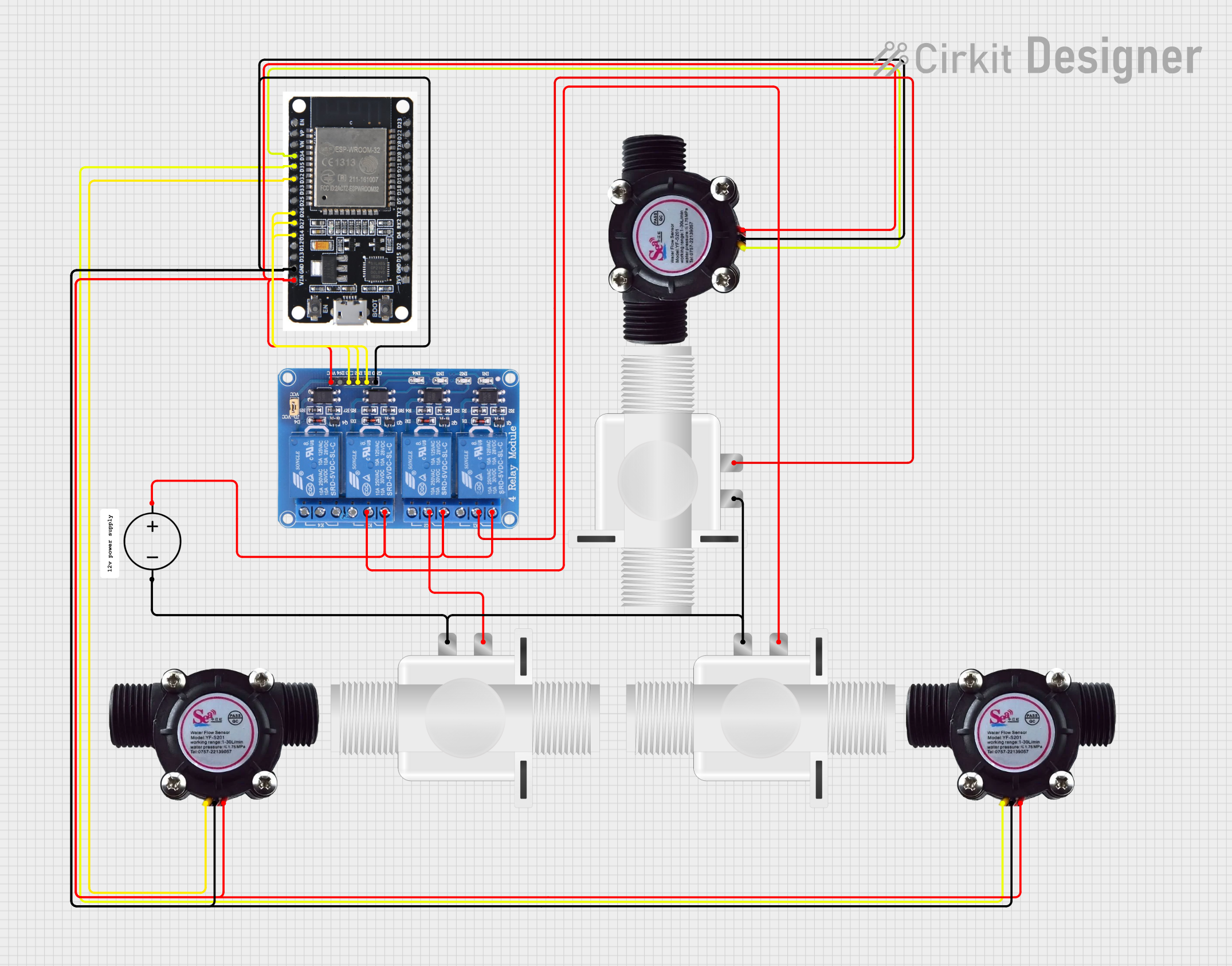
Circuit Documentation
Summary
This circuit is a water management system that uses an ESP32 microcontroller to monitor water flow through three different sensors and control three solenoid valves via a relay module. The system is connected to the Blynk platform for remote monitoring and control. The circuit includes the following components:
- ESP32 microcontroller
- Three water flow sensors
- Three plastic solenoid valves
- A 4-channel relay module
- A DC power source
Component List
ESP32
- Description: A powerful microcontroller with built-in Wi-Fi and Bluetooth capabilities.
- Pins: EN, VP, VN, D34, D35, D32, D33, D25, D26, D27, D14, D12, D13, GND, VIN, 3V3, D15, D2, D4, RX2, TX2, D5, D18, D19, D21, RX0, TX0, D22, D23, BOOT
Water Flow Sensor (3 units)
- Description: Measures the rate of water flow.
- Pins: Signal, Vcc, GND
Plastic Solenoid Valve (3 units)
- Description: Controls the flow of water.
- Pins: pin1, pin2
Relay 4 Channel 5v
- Description: Controls the solenoid valves.
- Pins: GND, IN1, IN2, IN3, IN4, VCC, COM1, COM2, COM3, COM4, NO1, NO2, NO3, NO4, NC1, NC2, NC3, NC4
DC Power Source
- Description: Provides power to the circuit.
- Pins: Ground, Positive
Wiring Details
ESP32
- D34 connected to Signal of Water Flow Sensor 1
- D35 connected to Signal of Water Flow Sensor 2
- D32 connected to Signal of Water Flow Sensor 3
- D26 connected to IN1 of Relay 4 Channel 5v
- D27 connected to IN2 of Relay 4 Channel 5v
- D14 connected to IN3 of Relay 4 Channel 5v
- GND connected to GND of all Water Flow Sensors and Relay 4 Channel 5v
- VIN connected to Vcc of all Water Flow Sensors and Relay 4 Channel 5v
Water Flow Sensor 1
- Signal connected to D34 of ESP32
- Vcc connected to VIN of ESP32
- GND connected to GND of ESP32
Water Flow Sensor 2
- Signal connected to D35 of ESP32
- Vcc connected to VIN of ESP32
- GND connected to GND of ESP32
Water Flow Sensor 3
- Signal connected to D32 of ESP32
- Vcc connected to VIN of ESP32
- GND connected to GND of ESP32
Plastic Solenoid Valve 1
- pin1 connected to Ground of DC Power Source
- pin2 connected to COM1 of Relay 4 Channel 5v
Plastic Solenoid Valve 2
- pin1 connected to COM2 of Relay 4 Channel 5v
- pin2 connected to Ground of DC Power Source
Plastic Solenoid Valve 3
- pin1 connected to COM3 of Relay 4 Channel 5v
- pin2 connected to Ground of DC Power Source
Relay 4 Channel 5v
- IN1 connected to D26 of ESP32
- IN2 connected to D27 of ESP32
- IN3 connected to D14 of ESP32
- GND connected to GND of ESP32
- VCC connected to VIN of ESP32
- COM1 connected to pin2 of Plastic Solenoid Valve 1
- COM2 connected to pin1 of Plastic Solenoid Valve 2
- COM3 connected to pin1 of Plastic Solenoid Valve 3
- NC1 connected to Positive of DC Power Source
- NC2 connected to Positive of DC Power Source
- NC3 connected to Positive of DC Power Source
DC Power Source
- Ground connected to pin1 of Plastic Solenoid Valve 1
- Ground connected to pin2 of Plastic Solenoid Valve 2
- Ground connected to pin2 of Plastic Solenoid Valve 3
- Positive connected to NC1 of Relay 4 Channel 5v
- Positive connected to NC2 of Relay 4 Channel 5v
- Positive connected to NC3 of Relay 4 Channel 5v
Code Documentation
#define BLYNK_TEMPLATE_ID "TMPL6-k4Y4yi4"  // Template ID
#define BLYNK_TEMPLATE_NAME "Water Management System"  // Template Name

#define BLYNK_AUTH_TOKEN "53WZtIU0niLoFvGOzzkslbL0tceD3lu7"

#include <WiFi.h>
#include <BlynkSimpleEsp32.h>

// Wi-Fi credentials
const char *ssid = "Hello 2";             // Wi-Fi SSID
const char *password = "A245618A245872";  // Wi-Fi Password
char auth[] = "53WZtIU0niLoFvGOzzkslbL0tceD3lu7";  // Blynk Auth Token

// Flow Sensor Pins
const int mainFlowSensorPin = 34;  // GPIO for main flow sensor
const int user1FlowSensorPin = 35; // GPIO for user 1 flow sensor
const int user2FlowSensorPin = 32; // GPIO for user 2 flow sensor

// Relay Pins (for solenoids)
const int mainRelayPin = 26;  // Relay for main flow sensor
const int user1RelayPin = 27; // Relay for user 1 flow sensor
const int user2RelayPin = 14; // Relay for user 2 flow sensor

// Variables to store flow sensor counts
volatile int mainFlowCount = 0;
volatile int user1FlowCount = 0;
volatile int user2FlowCount = 0;

// Flow rates in liters per minute
float mainFlowRate = 0;
float user1FlowRate = 0;
float user2FlowRate = 0;

// Flag to indicate leak
bool leakDetected = false;

// Pulse counters for calculating flow rate
void IRAM_ATTR countMainFlow() { mainFlowCount++; }
void IRAM_ATTR countUser1Flow() { user1FlowCount++; }
void IRAM_ATTR countUser2Flow() { user2FlowCount++; }

// Blynk virtual pins to control relays
BLYNK_WRITE(V1) {
  int state = param.asInt();
  if (state == 1) {
    digitalWrite(mainRelayPin, LOW);  // Relay ON (active LOW)
    Serial.println("Main solenoid opened (Relay ON)");
  } else {
    digitalWrite(mainRelayPin, HIGH); // Relay OFF (active LOW)
    Serial.println("Main solenoid closed (Relay OFF)");
  }
}

BLYNK_WRITE(V2) {
  int state = param.asInt();
  if (state == 1) {
    digitalWrite(user1RelayPin, LOW);  // Relay ON (active LOW)
    Serial.println("User 1 solenoid opened (Relay ON)");
  } else {
    digitalWrite(user1RelayPin, HIGH); // Relay OFF (active LOW)
    Serial.println("User 1 solenoid closed (Relay OFF)");
  }
}

BLYNK_WRITE(V3) {
  int state = param.asInt();
  if (state == 1) {
    digitalWrite(user2RelayPin, LOW);  // Relay ON (active LOW)
    Serial.println("User 2 solenoid opened (Relay ON)");
  } else {
    digitalWrite(user2RelayPin, HIGH); // Relay OFF (active LOW)
    Serial.println("User 2 solenoid closed (Relay OFF)");
  }
}

void setup() {
  Serial.begin(115200);

  // Initialize flow sensor pins
  pinMode(mainFlowSensorPin, INPUT_PULLUP);
  pinMode(user1FlowSensorPin, INPUT_PULLUP);
  pinMode(user2FlowSensorPin, INPUT_PULLUP);

  // Initialize relay pins
  pinMode(mainRelayPin, OUTPUT);
  pinMode(user1RelayPin, OUTPUT);
  pinMode(user2RelayPin, OUTPUT);

  // Set relays to OFF initially (solenoids closed)
  digitalWrite(mainRelayPin, HIGH);  // Active LOW