
Arduino Mega 2560 Based GPS and Environmental Data Logger with LCD Display
View and Edit Project In Cirkit Designer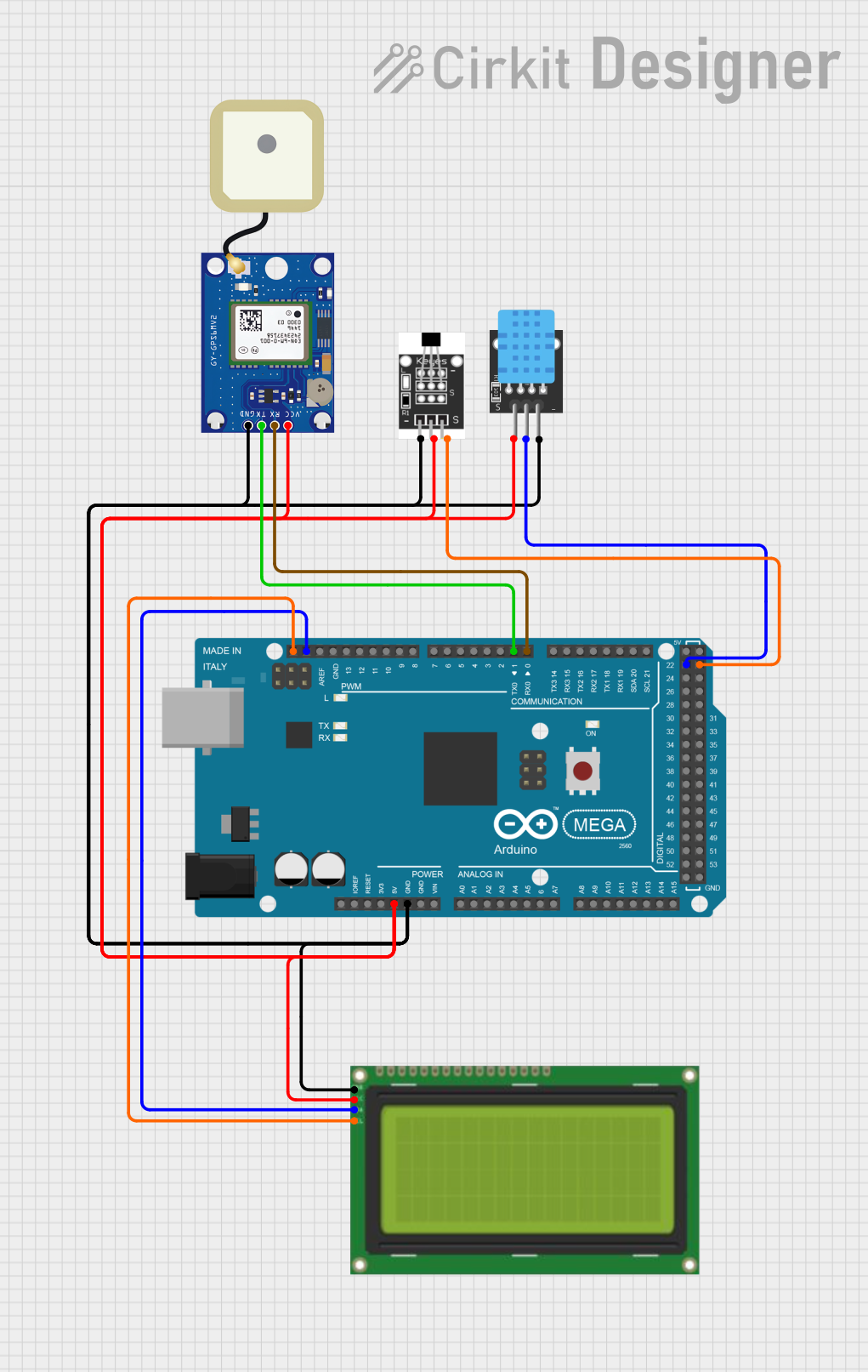
Circuit Documentation
Summary
This circuit integrates multiple components, including an Arduino Mega 2560 microcontroller, an LCD 20x4 with I2C interface, a Hall sensor, a DHT11 temperature and humidity sensor, and a GPS NEO-6M V2 module. The Arduino Mega 2560 serves as the central processing unit, interfacing with the sensors and the LCD to display data or perform other functions as programmed. The GPS module provides location data, the Hall sensor detects magnetic fields, and the DHT11 sensor measures environmental conditions. The LCD displays information to the user. Power distribution is managed through common 5V and GND nets, and communication between devices is established via digital and I2C connections.
Component List
Arduino Mega 2560
- Microcontroller board based on the ATmega2560
- Offers numerous digital and analog I/O pins
- Supports I2C, SPI, and serial communication
Lcd 20x4 i2c
- Alphanumeric LCD display with 20 characters by 4 lines
- I2C communication interface for reduced pin usage
- Backlit for visibility in low-light conditions
Hall Sensor
- Magnetic field sensor
- Provides digital output in response to magnetic field changes
- Requires power and a single digital input to the microcontroller
DHT11
- Combined temperature and humidity sensor
- Provides digital output for interfacing with microcontrollers
- Low power consumption and easy to interface
GPS NEO-6M V2
- GPS module for location tracking
- Communicates with microcontroller via serial interface
- Requires power and two digital pins for RX/TX communication
Wiring Details
Arduino Mega 2560
- 5V: Connected to the 5V power supply net
- GND: Connected to the ground net
- D0 RX0: Connected to TX pin of GPS NEO-6M V2
- D1 TX0: Connected to RX pin of GPS NEO-6M V2
- SDA: Connected to SCA pin of Lcd 20x4 i2c
- SCL: Connected to SCL pin of Lcd 20x4 i2c
- D22: Connected to S pin of DHT11
- D23: Connected to S pin of Hall Sensor
Lcd 20x4 i2c
- GND: Connected to the ground net
- 5v: Connected to the 5V power supply net
- SCA: Connected to SDA pin of Arduino Mega 2560
- SCL: Connected to SCL pin of Arduino Mega 2560
Hall Sensor
- -: Connected to the ground net
- +: Connected to the 5V power supply net
- S: Connected to D23 pin of Arduino Mega 2560
DHT11
- GND: Connected to the ground net
- 5V: Connected to the 5V power supply net
- S: Connected to D22 pin of Arduino Mega 2560
GPS NEO-6M V2
- GND: Connected to the ground net
- VCC: Connected to the 5V power supply net
- RX: Connected to D0 RX0 pin of Arduino Mega 2560
- TX: Connected to D1 TX0 pin of Arduino Mega 2560
Documented Code
Arduino Mega 2560 - sketch.ino
void setup() {
  // put your setup code here, to run once:

}

void loop() {
  // put your main code here, to run repeatedly:

}
Arduino Mega 2560 - documentation.txt
(No additional documentation provided)