
Circuit Documentation
Summary of the Circuit
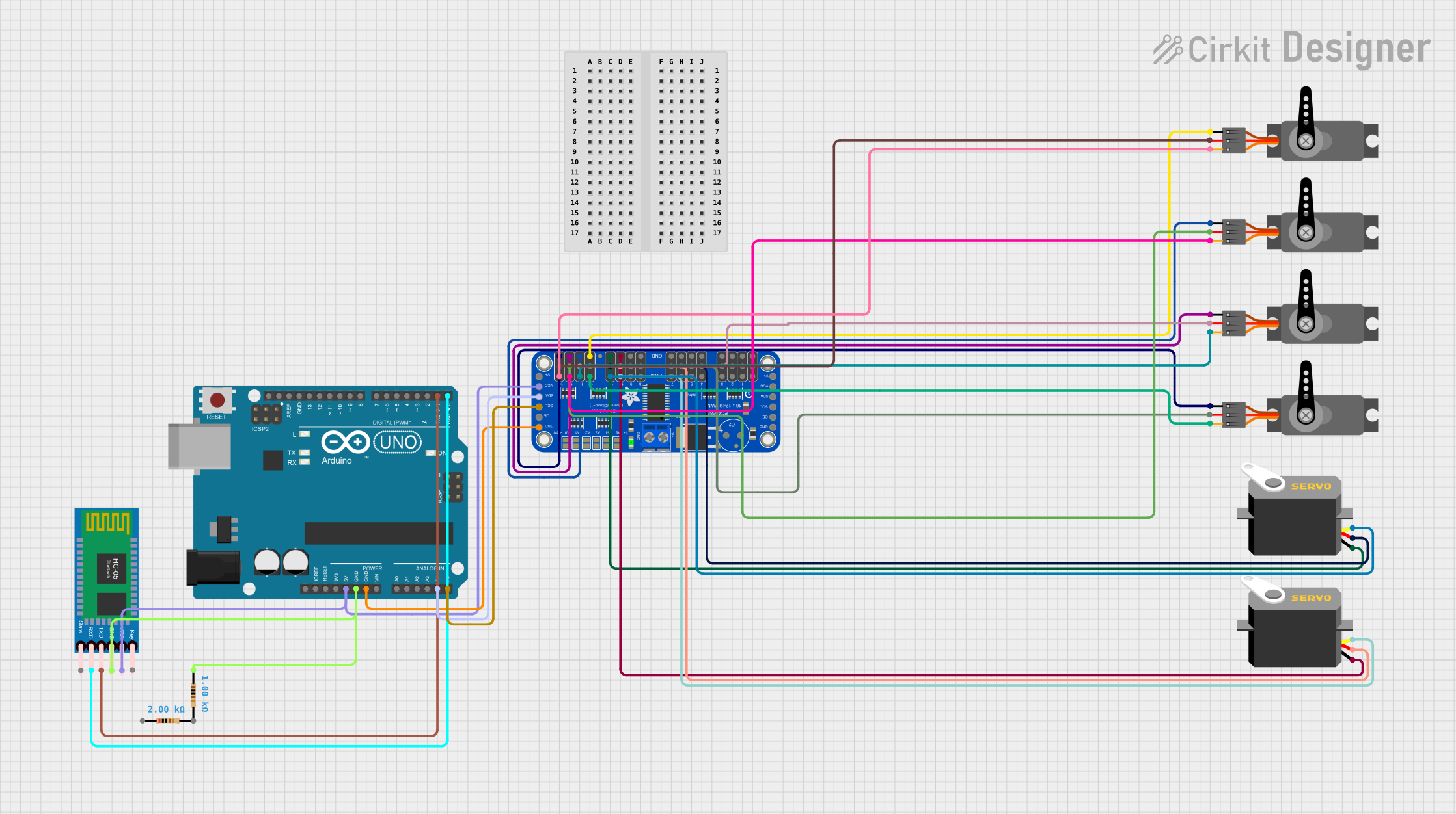
This circuit is designed to control multiple servo motors using an Arduino UNO microcontroller and an Adafruit 16-Channel 12-bit PWM Servo Driver. The circuit also includes an HC-05 Bluetooth module for wireless communication, which can be used to receive commands to control the servos. The servos are powered by the PWM Servo Driver, which is in turn powered by the 5V output from the Arduino UNO. The Arduino communicates with the PWM Servo Driver via I2C protocol, using its A4 and A5 pins for SDA and SCL lines, respectively. The HC-05 Bluetooth module is interfaced with the Arduino through the RX and TX pins for serial communication. Additionally, resistors are included for potential voltage division or current limiting purposes.
Component List
Arduino UNO
- Microcontroller board based on the ATmega328P
- Features digital I/O pins, analog input pins, and various power pins
- Utilized for controlling the PWM Servo Driver and communicating with the HC-05 Bluetooth module
Adafruit 16-Channel 12-bit PWM Servo Driver - I2C
- I2C-enabled PWM driver capable of controlling 16 servos with 12-bit resolution
- Powered by the 5V supply from the Arduino UNO
- Receives control signals from the Arduino via the I2C bus
Servo Motors
- Multiple servos controlled by the PWM outputs of the Servo Driver
- Each servo has a ground (GND), power (VCC), and control (PWM or pulse) pin
HC-05 Bluetooth Module
- Wireless communication module using Bluetooth protocol
- Powered by the 5V supply from the Arduino UNO
- Communicates with the Arduino via serial communication (RX/TX)
Resistors
- Passive components used for current limiting or voltage division
- Different resistances used in the circuit (e.g., 1000 Ohms, 2000 Ohms)
Wiring Details
Arduino UNO
- 5V to Servo Driver VCC and Bluetooth Module VCC
- GND to Servo Driver GND, Bluetooth Module GND, and one terminal of each resistor
- A4 (SDA) to Servo Driver SDA
- A5 (SCL) to Servo Driver SCL
- D0 (RX) to Bluetooth Module TXD
- D1 (TX) to Bluetooth Module RXD
Adafruit 16-Channel 12-bit PWM Servo Driver - I2C
- VCC to Arduino 5V
- GND to Arduino GND and all Servo GND pins
- SDA to Arduino A4
- SCL to Arduino A5
- PWM outputs to corresponding Servo control pins
Servo Motors
- GND to Servo Driver GND
- VCC to Servo Driver 5.0V
- PWM or pulse to corresponding Servo Driver PWM outputs
HC-05 Bluetooth Module
- VCC to Arduino 5V
- GND to Arduino GND (through a resistor)
- TXD to Arduino D0
- RXD to Arduino D1
Resistors
- One terminal connected to Arduino GND
- Other terminal connected to Bluetooth Module GND (specific resistor values not detailed in the wiring list)
Documented Code
Arduino UNO Code (sketch.ino)
void setup() {
  // put your setup code here, to run once:

}

void loop() {
  // put your main code here, to run repeatedly:

}
Additional Notes
- The provided code for the Arduino UNO is a template with empty setup and loop functions. Actual implementation code for controlling the servos and handling Bluetooth communication needs to be added.
- The documentation file for the Arduino code is empty and should be populated with relevant information as the code is developed.