
ESP32-Based Smart Parking System with Ultrasonic Sensors and LCD Display
View and Edit Project In Cirkit Designer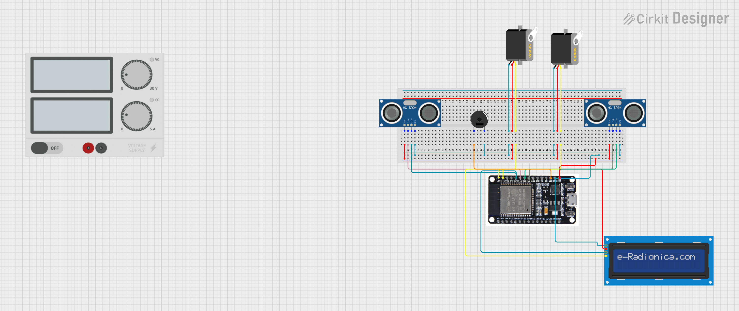
Circuit Documentation
Summary
This circuit is designed to manage a parking system using an ESP32 microcontroller. It includes components such as ultrasonic sensors for distance measurement, a piezo buzzer for alerts, servos for gate control, and an LCD screen for displaying the status of parking slots. The system also integrates with Blynk for remote monitoring and control.
Component List
LCD screen 16x2 I2C
- Pins: SCL, SDA, VCC, GND
- Description: A 16x2 character LCD display with I2C interface.
- Purpose: Displays the status of parking slots.
Piezo Buzzer
- Pins: pin 1, pin 2
- Description: A simple piezoelectric buzzer.
- Purpose: Provides audible alerts when a car parks.
Servo
- Pins: gnd, vcc, pulse
- Description: A standard servo motor.
- Purpose: Controls the entrance and exit gates.
HC-SR04 Ultrasonic Sensor
- Pins: VCC, TRIG, ECHO, GND
- Description: An ultrasonic distance sensor.
- Purpose: Measures the distance to detect the presence of cars in parking slots.
Power Supply
- Pins: +, -
- Description: Provides power to the circuit.
- Purpose: Supplies power to all components.
ESP32
- Pins: EN, VP, VN, D34, D35, D32, D33, D25, D26, D27, D14, D12, D13, GND, VIN, 3V3, D15, D2, D4, RX2, TX2, D5, D18, D19, D21, RX0, TX0, D22, D23, BOOT
- Description: A powerful microcontroller with WiFi and Bluetooth capabilities.
- Purpose: Acts as the main controller for the circuit, handling all logic and communication.
Wiring Details
LCD screen 16x2 I2C
- SCL connected to ESP32 D22
- SDA connected to ESP32 D21
- VCC connected to ESP32 3V3
- GND connected to ESP32 GND
Piezo Buzzer
- pin 1 connected to ESP32 D15
- pin 2 connected to GND
Servo (Entrance Gate)
- gnd connected to GND
- vcc connected to 3V3
- pulse connected to ESP32 D23
Servo (Exit Gate)
- gnd connected to GND
- vcc connected to 3V3
- pulse connected to ESP32 D22
HC-SR04 Ultrasonic Sensor (Slot 1)
- VCC connected to 3V3
- TRIG connected to ESP32 D5
- ECHO connected to ESP32 D18
- GND connected to GND
HC-SR04 Ultrasonic Sensor (Slot 2)
- VCC connected to 3V3
- TRIG connected to ESP32 D19
- ECHO connected to ESP32 D21
- GND connected to GND
Power Supply
- + connected to 3V3
- - connected to GND
Code Documentation
// Include libraries
#include <Wire.h>
#include <LiquidCrystal_I2C.h>
#include <Servo.h>
#include <WiFi.h>
#include <BlynkSimpleEsp32.h>

// Define hardware pins
#define TRIG1 5
#define ECHO1 18
#define TRIG2 19
#define ECHO2 21
#define BUZZER 2
#define LED_SLOT1 15
#define LED_SLOT2 4
#define SERVO_ENTRANCE 13
#define SERVO_EXIT 12

// Constants
const int DISTANCE_THRESHOLD = 10; // in cm

// Create objects
LiquidCrystal_I2C lcd(0x27, 16, 2); // I2C LCD
Servo entranceServo;
Servo exitServo;

// Blynk credentials
char auth[] = "YourAuthToken"; // Replace with your Blynk Auth Token
char ssid[] = "YourWiFiSSID";  // Replace with your WiFi SSID
char pass[] = "YourWiFiPassword"; // Replace with your WiFi password

// Variables
bool slot1Occupied = false;
bool slot2Occupied = false;

// Function to measure distance
long measureDistance(int trigPin, int echoPin) {
  digitalWrite(trigPin, LOW);
  delayMicroseconds(2);
  digitalWrite(trigPin, HIGH);
  delayMicroseconds(10);
  digitalWrite(trigPin, LOW);

  long duration = pulseIn(echoPin, HIGH);
  long distance = duration * 0.034 / 2; // Convert to cm
  return distance;
}

void setup() {
  // Initialize Serial Monitor
  Serial.begin(115200);

  // Initialize LCD
  lcd.init();
  lcd.backlight();

  // Initialize Ultrasonic Sensors
  pinMode(TRIG1, OUTPUT);
  pinMode(ECHO1, INPUT);
  pinMode(TRIG2, OUTPUT);
  pinMode(ECHO2, INPUT);

  // Initialize Buzzer and LEDs
  pinMode(BUZZER, OUTPUT);
  pinMode(LED_SLOT1, OUTPUT);
  pinMode(LED_SLOT2, OUTPUT);

  // Initialize Servos
  entranceServo.attach(SERVO_ENTRANCE);
  exitServo.attach(SERVO_EXIT);
  entranceServo.write(0); // Entrance gate closed
  exitServo.write(0);     // Exit gate closed

  // Connect to WiFi and Blynk
  WiFi.begin(ssid, pass);
  while (WiFi.status() != WL_CONNECTED) {
    delay(500);
    Serial.print(".");
  }
  Serial.println("WiFi connected!");
  Blynk.begin(auth, ssid, pass);
}

void loop() {
  Blynk.run();

  // Measure distances for both slots
  long distance1 = measureDistance(TRIG1, ECHO1);
  long distance2 = measureDistance(TRIG2, ECHO2);

  // Update slot status and LEDs
  slot1Occupied = (distance1 < DISTANCE_THRESHOLD);
  slot2Occupied = (distance2 < DISTANCE_THRESHOLD);

  digitalWrite(LED_SLOT1, slot1Occupied ? HIGH : LOW);
  digitalWrite(LED_SLOT2, slot2Occupied ? HIGH : LOW);

  // Display status on LCD
  lcd.setCursor(0, 0);
  lcd.print("Slot1: ");
  lcd.print(slot1Occupied ? "Occupied" : "Free");
  lcd.setCursor(0, 1);
  lcd.print("Slot2: ");
  lcd.print(slot2Occupied ? "Occupied" : "Free");

  // Trigger buzzer if a new car parks
  if (slot1Occupied || slot2Occupied) {
    digitalWrite(BUZZER, HIGH);
    delay(3000);
    digitalWrite(BUZZER, LOW);
  }

  // Example: Open entrance gate when slot is free
  if (!slot1Occupied || !slot2Occupied) {
    entranceServo.write(90); // Open entrance gate
    delay(2000);
    entranceServo.write(0);  // Close entrance gate
  }

  // Example: Open exit gate (manually triggered)
  // Add Blynk functionality to trigger exit gate remotely
}

// Add Blynk Virtual Pin handlers (Optional for more control)
This documentation provides a comprehensive overview of the circuit, including a summary, detailed component list, wiring details, and the embedded code.