
ESP8266 NodeMCU Controlled Multi-Channel Thermocouple Interface
View and Edit Project In Cirkit Designer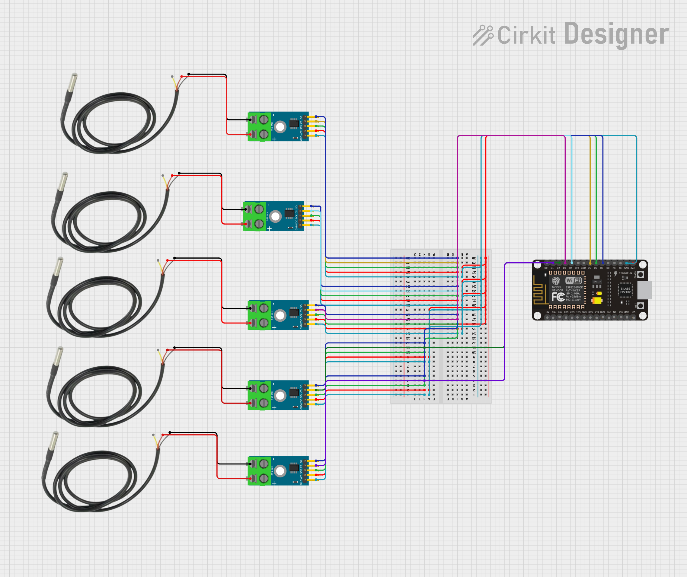
Circuit Documentation
Summary
The circuit in question is designed to interface multiple MAX6675 thermocouple-to-digital converter modules with an ESP8266 NodeMCU microcontroller. The MAX6675 modules are used to read temperatures from K-type thermocouples, and the ESP8266 NodeMCU is used to process these readings. The circuit is powered by the 3.3V supply from the ESP8266 NodeMCU, which is distributed to the MAX6675 modules. Ground connections are shared among all components to complete the power circuit. The SPI interface of the ESP8266 NodeMCU is used to communicate with the MAX6675 modules, with separate chip select (CS) lines for each module to enable individual addressing. Additionally, each MAX6675 module is connected to a temperature sensor.
Component List
MAX6675 Module
- Description: A thermocouple-to-digital converter module that allows K-type thermocouples to interface with microcontrollers.
- Pins: GND, VCC, SCK, CS, SO, -, +
Temperature Sensor
- Description: A sensor that measures temperature and provides data to the MAX6675 module.
- Pins: Temp GND Black, Temp VDD Red, Temp DQ Data Yellow
ESP8266 NodeMCU
- Description: A microcontroller board with Wi-Fi capability, used for processing and communicating sensor data.
- Pins: D0, D1, D2, D3, D4, 3V3, GND, D5, D6, D7, D8, RX, TX, A0, RSV, SD3, SD2, SD1, CMD, SD0, CLK, EN, RST, VIN
Wiring Details
MAX6675 Module
- GND: Connected to the common ground.
- VCC: Connected to the 3.3V power supply from the ESP8266 NodeMCU.
- SCK: Connected to the D6 pin of the ESP8266 NodeMCU for the SPI clock.
- CS: Connected to individual GPIO pins (D1, D2, D3, D4, D5) on the ESP8266 NodeMCU for chip select functionality.
- SO: Connected to the D7 pin of the ESP8266 NodeMCU for SPI data output.
- -: Connected to the Temp GND Black pin of the corresponding Temperature Sensor.
- +: Connected to the Temp VDD Red pin of the corresponding Temperature Sensor.
Temperature Sensor
- Temp GND Black: Connected to the '-' pin of the corresponding MAX6675 Module.
- Temp VDD Red: Connected to the '+' pin of the corresponding MAX6675 Module.
- Temp DQ Data Yellow: Not connected in the provided net list.
ESP8266 NodeMCU
- GND: Connected to the common ground.
- 3V3: Provides the 3.3V power supply to the MAX6675 Modules.
- D1, D2, D3, D4, D5: Used as chip select (CS) pins for the MAX6675 Modules.
- D6: Used as the SPI clock (SCK) for the MAX6675 Modules.
- D7: Used as the SPI data output (SO) for the MAX6675 Modules.
Documented Code
No code was provided in the input. Typically, the code for the ESP8266 NodeMCU would initialize the SPI interface, read temperature data from the MAX6675 modules, and possibly send the data to a remote server or display it locally. However, without the actual code, we cannot provide further documentation on the software aspect of this circuit.