Transistor-Based Motor Speed Regulation Circuit
Circuit Documentation
Summary of the Circuit
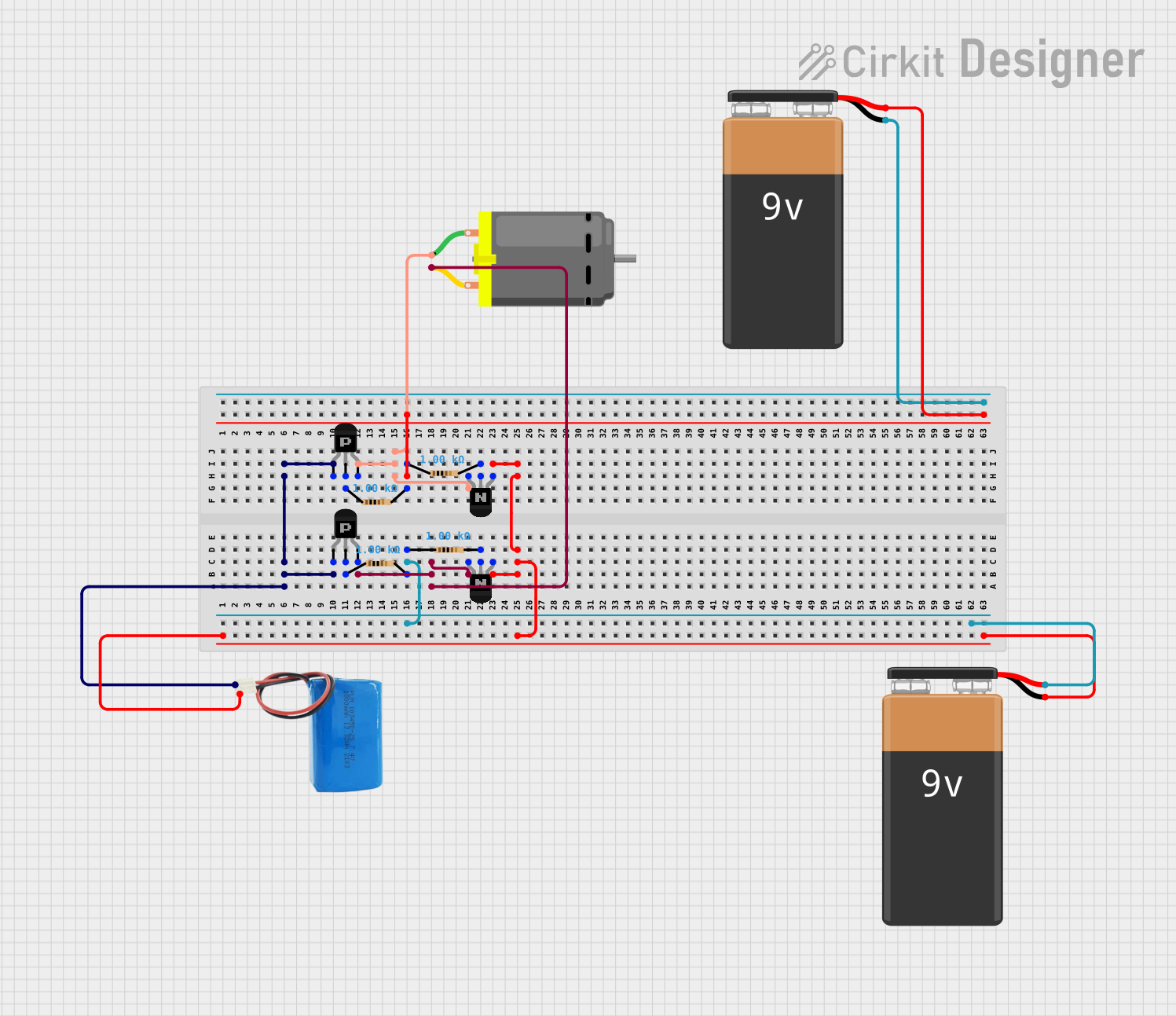
This circuit appears to be a motor control circuit utilizing a combination of PNP and NPN transistors to drive a DC motor. The circuit includes two 9V batteries and a 5V battery, which suggests that different parts of the circuit operate at different voltage levels. The transistors are likely arranged in a push-pull configuration to control the motor's direction or speed. The resistors in the circuit are probably used to limit current or to set the base biasing for the transistors. Since there is no microcontroller code provided, the circuit is likely to be a simple analog control circuit without programmable control features.
Component List
9V Battery
- Description: Provides a 9V power supply to the circuit.
PNP Transistor (EBC)
- Description: A PNP bipolar junction transistor with emitter, base, and collector pins.
NPN Transistor (EBC)
- Description: An NPN bipolar junction transistor with emitter, base, and collector pins.
Resistor (1k Ohm)
- Description: A resistor with a resistance of 1000 Ohms, used for current limiting or voltage division.
5V Battery
- Description: Provides a 5V power supply to the circuit.
DC Motor
- Description: An electric motor that runs on direct current (DC) electricity.
Wiring Details
9V Battery
- Positive terminal connected to the positive terminal of another 9V battery.
- Negative terminal connected to the negative terminal of the 5V battery and the emitters of both NPN transistors.
PNP Transistor (EBC)
- Emitter of both PNP transistors connected to the positive terminal of the 5V battery.
- Collector of one PNP transistor connected to the collector of one NPN transistor and pin 2 of the DC motor.
- Collector of the other PNP transistor connected to the collector of the other NPN transistor and pin 1 of the DC motor.
- Base of one PNP transistor connected to a 1k Ohm resistor.
- Base of the other PNP transistor connected to another 1k Ohm resistor.
NPN Transistor (EBC)
- Emitter of both NPN transistors connected to the negative terminals of the 5V battery and one of the 9V batteries.
- Collector of one NPN transistor connected to the collector of one PNP transistor and pin 2 of the DC motor.
- Collector of the other NPN transistor connected to the collector of the other PNP transistor and pin 1 of the DC motor.
- Base of one NPN transistor connected to a 1k Ohm resistor.
- Base of the other NPN transistor connected to another 1k Ohm resistor.
Resistor (1k Ohm)
- One end of two resistors connected to the positive terminal of a 9V battery.
- The other end of one resistor connected to the base of one NPN transistor.
- The other end of the other resistor connected to the base of the other NPN transistor.
- One end of two resistors connected to the base of each PNP transistor.
- The other end of one resistor connected to the base of one NPN transistor.
- The other end of the other resistor connected to the base of the other NPN transistor.
5V Battery
- Positive terminal connected to the emitters of both PNP transistors.
- Negative terminal connected to the emitters of both NPN transistors and the negative terminal of one of the 9V batteries.
DC Motor
- Pin 1 connected to the collector of one PNP transistor and the collector of one NPN transistor.
- Pin 2 connected to the collector of the other PNP transistor and the collector of the other NPN transistor.
Documented Code
No code has been provided for this circuit. This section is reserved for future use if programmable components are added to the circuit.