ESP32-Based Smart Garbage Monitoring System with Ultrasonic Sensing and Traffic Light Indicators
Circuit Documentation
Summary
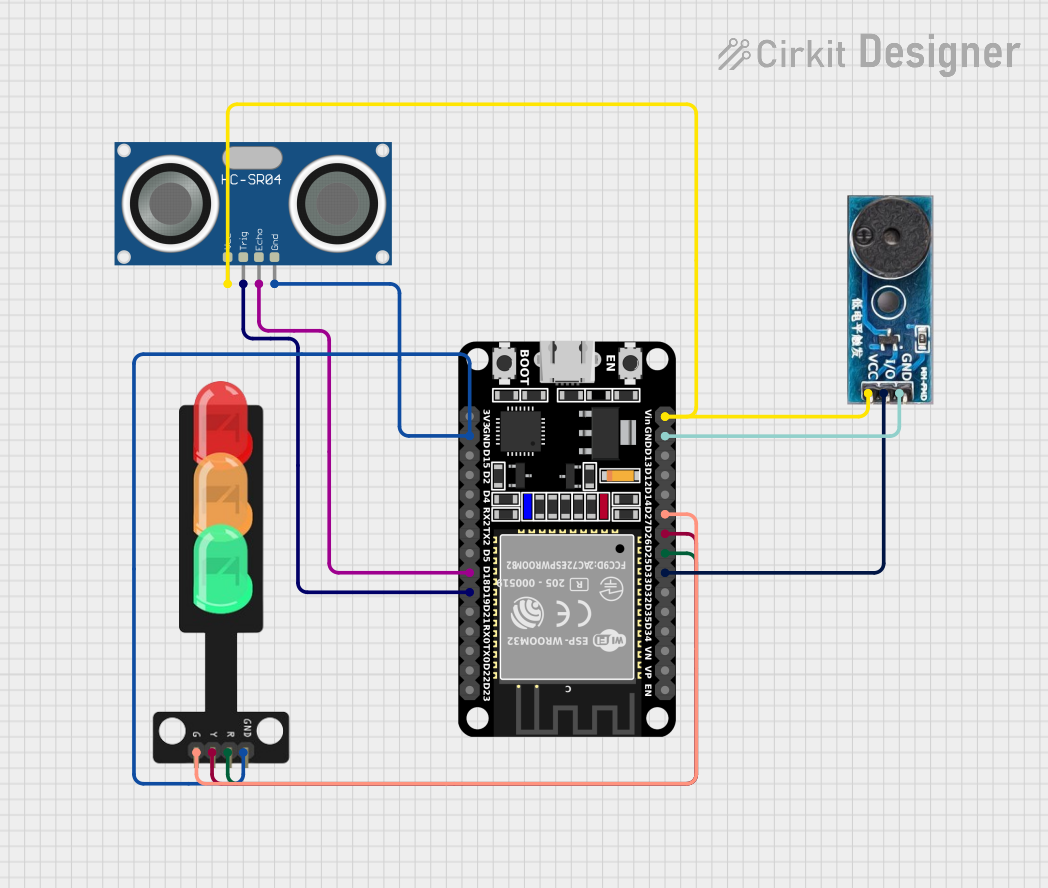
The circuit in question is designed to interface an ESP32 microcontroller with a buzzer module, an HC-SR04 ultrasonic sensor, and a traffic light module. The ESP32 is responsible for controlling the buzzer and the traffic light LEDs based on the distance measurements from the ultrasonic sensor. The circuit is likely intended for a smart garbage maintaining system, as indicated by the embedded code, which suggests functionality for detecting the fill level of a container and alerting when the container is full.
Component List
ESP32 (30 pin)
- Description: A microcontroller with Wi-Fi capabilities, featuring a wide range of GPIO pins for interfacing with various sensors and modules.
- Pins: EN, VP, VN, D34, D35, D32, D33, D25, D26, D27, D14, D12, D13, GND, Vin, D23, D22, TX0, RX0, D21, D19, D18, D5, TX2, RX2, D4, D2, D15, 3V3
Buzzer Module
- Description: An electronic buzzer that can produce an audible tone when powered.
- Pins: GND, Vcc, I/O
HC-SR04 Ultrasonic Sensor
- Description: A sensor that measures distance by emitting ultrasonic waves and measuring the time taken for the echo to return.
- Pins: VCC, TRIG, ECHO, GND
Traffic Light
- Description: A module with three LEDs (Red, Yellow, Green) that simulates a traffic light.
- Pins: Green, Yellow, Red, GND
Wiring Details
ESP32 (30 pin)
- D33: Connected to the I/O pin of the Buzzer Module.
- D25: Connected to the Red pin of the Traffic Light.
- D26: Connected to the Yellow pin of the Traffic Light.
- D27: Connected to the Green pin of the Traffic Light.
- GND: Common ground shared with the Buzzer Module, HC-SR04 Ultrasonic Sensor, and Traffic Light.
- Vin: Connected to the Vcc pin of the Buzzer Module and VCC pin of the HC-SR04 Ultrasonic Sensor.
- D19: Connected to the TRIG pin of the HC-SR04 Ultrasonic Sensor.
- D18: Connected to the ECHO pin of the HC-SR04 Ultrasonic Sensor.
Buzzer Module
- GND: Connected to the GND pin of the ESP32.
- Vcc: Connected to the Vin pin of the ESP32.
- I/O: Connected to the D33 pin of the ESP32.
HC-SR04 Ultrasonic Sensor
- VCC: Connected to the Vin pin of the ESP32.
- TRIG: Connected to the D19 pin of the ESP32.
- ECHO: Connected to the D18 pin of the ESP32.
- GND: Connected to the GND pin of the ESP32.
Traffic Light
- Red: Connected to the D25 pin of the ESP32.
- Yellow: Connected to the D26 pin of the ESP32.
- Green: Connected to the D27 pin of the ESP32.
- GND: Connected to the GND pin of the ESP32.
Documented Code
#define BLYNK_TEMPLATE_ID "TMPL3_mZ5JXni"
#define BLYNK_TEMPLATE_NAME "Smart Garbage Maintaining System"
#define BLYNK_AUTH_TOKEN "yrA62Lf3TT-rvYpnep6P5okcO-021lWy"
#define PIN_RED    25 // The ESP32 pin GPIO25 connected to R pin of traffic light module
#define PIN_YELLOW 26 // The ESP32 pin GPIO26 connected to Y pin of traffic light module
#define PIN_GREEN  27 // The ESP32 pin GPIO27 connected to G pin of traffic light module

#define RED_TIME     500 // RED time in millisecond
#define YELLOW_TIME  500 // YELLOW time in millisecond
#define GREEN_TIME   500 // GREEN time in millisecond

#include <LiquidCrystal_I2C.h>
#include <Wire.h>
#include <WiFi.h>
#include <WiFiClient.h>
#include <BlynkSimpleEsp32.h>
#include <NewPing.h>
#define TRIGGER_PIN  19  // ESP32 pin tied to trigger pin on the ultrasonic sensor.
#define ECHO_PIN     18  // ESP32 pin tied to echo pin on the ultrasonic sensor.
#define MAX_DISTANCE 200 // Maximum distance we want to ping for (in centimeters).

BlynkTimer timer; // Creating a timer object

char ssid[] = "Training Hall_EXT";
char pass[] = "IRDT#1982";

LiquidCrystal_I2C lcd(0x27, 20, 4);  // set the LCD address to 0x27 for a 16 chars and 2 line display
NewPing sonar(TRIGGER_PIN, ECHO_PIN, MAX_DISTANCE); // NewPing setup of pins and maximum distance.

const int buzzerPin = 23;
int bucketFilledUpto = 0;

void setup() {
  Serial.begin(115200); // Starts the serial communication

  lcd.init();
  lcd.backlight();
  show(0);
  pinMode(buzzerPin, OUTPUT);
  digitalWrite(buzzerPin, HIGH);
  timer.setInterval(1000L, myTimerEvent); //Starting a timer
  Blynk.begin(BLYNK_AUTH_TOKEN, ssid, pass);
  pinMode(PIN_RED, OUTPUT);
  pinMode(PIN_YELLOW, OUTPUT);
  pinMode(PIN_GREEN, OUTPUT);
}

void myTimerEvent() // This loop defines what happens when timer is triggered
{
  Blynk.virtualWrite(V0, bucketFilledUpto);
}

void loop() {
  delay(50); // Wait 50ms between pings (about 20 pings/sec).
  float distanceCm = sonar.ping_cm();

  Serial.print(bucketFilledUpto);
  Serial.print("Ping: ");
  Serial.print(distanceCm); // Send ping, get distance in cm and print result (0 = outside set distance range)
  Serial.println("cm");
  digitalWrite(PIN_RED, LOW);    // turn off
  digitalWrite(PIN_YELLOW, LOW); // turn off
  bucketFilledUpto = ((18 - distanceCm) * 100) / 18;
  show(bucketFilledUpto);
  if (distanceCm <= 5) {
    digitalWrite(buzzerPin, LOW);
    digitalWrite(PIN_RED, HIGH);    // turn on
    digitalWrite(PIN_YELLOW, LOW); // turn off
    digitalWrite(PIN_GREEN, LOW); // turn off
    delay(500);
  } else {
    digitalWrite(buzzerPin, HIGH);
    digitalWrite(PIN_RED, LOW);    // turn off
    digitalWrite(PIN_YELLOW, LOW); // turn off
    digitalWrite(PIN_GREEN, HIGH); // turn on
    delay(500);
  }

  Blynk.run();
  timer.run();
}

void show(float d) {
  lcd.setCursor(0, 0);
  lcd.print("Name : Anand,Anshu");
  lcd.setCursor(0, 1);
  lcd.print("Member: 3");
  lcd.setCursor(0, 2);
  lcd.print("Project Name: GMS");
  lcd.setCursor(0, 3);
  lcd.print("Status :");
  lcd.setCursor(10, 3);
  lcd.print(d);
  lcd.print("%");
}
This code is designed to run on an ESP32 microcontroller. It uses the Blynk platform for IoT applications, an LCD for display, and a NewPing library for the ultrasonic sensor. The code manages the traffic light LEDs and the buzzer based on the distance measured by the ultrasonic sensor, indicating the fill level of a container. The Blynk platform is used to send the fill level data to a virtual pin for remote monitoring.