
Arduino UNO-Based Stepper Motor Controller with Keypad and LCD Display
View and Edit Project In Cirkit Designer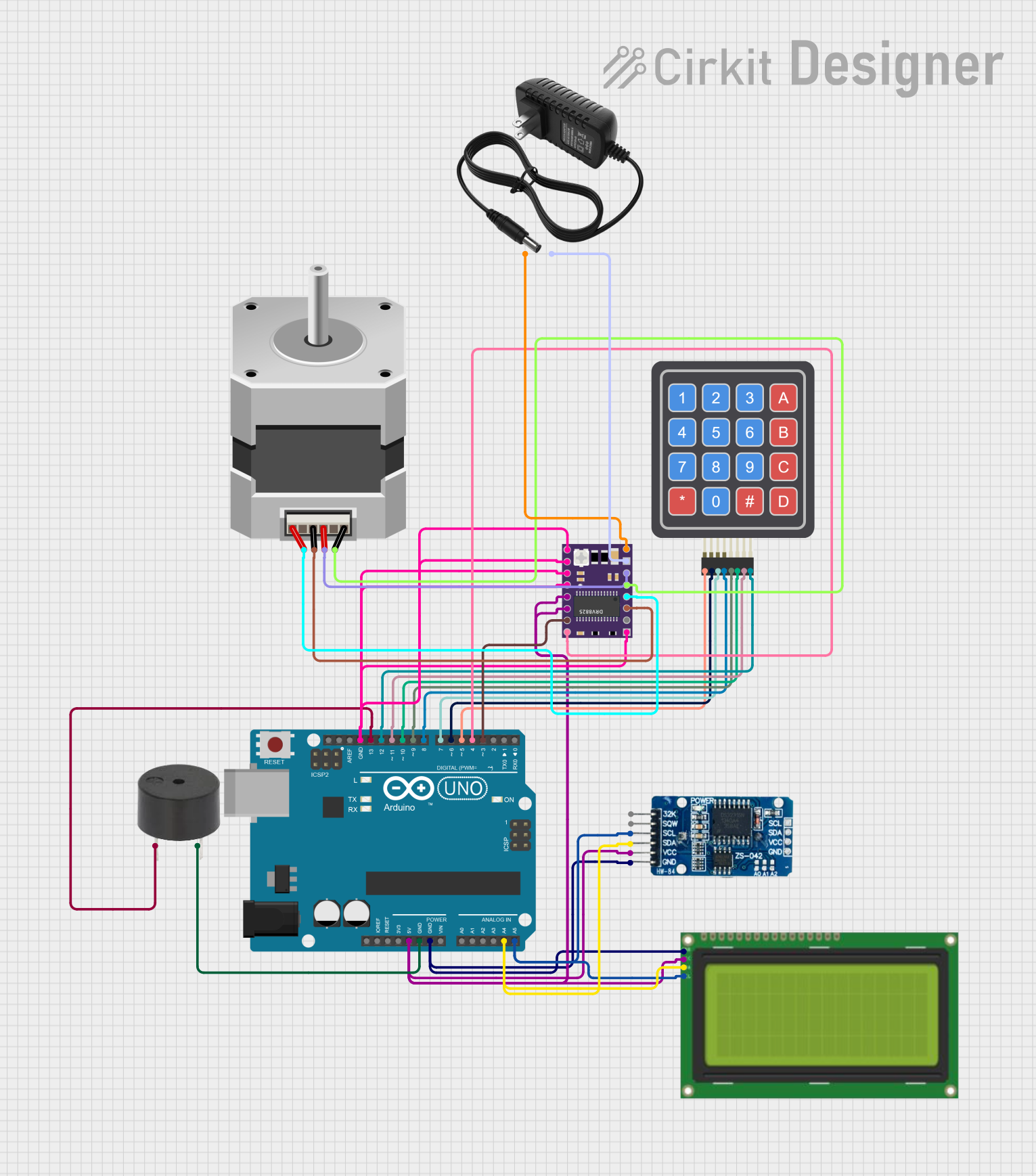
Circuit Documentation
Summary
This circuit involves an Arduino UNO microcontroller interfacing with various components including a stepper motor, a buzzer, an LCD display, a keypad, an RTC module, a stepper motor driver, and a 12V power supply. The Arduino UNO serves as the central controller, managing the operations of the connected components.
Component List
Stepper Motor (Bipolar)
- Description: A bipolar stepper motor used for precise control of rotational position.
- Pins: D, B, C, A
Buzzer
- Description: An audio signaling device.
- Pins: PIN, GND
LCD 20x4 I2C
- Description: A 20x4 character LCD display with I2C interface.
- Pins: GND, 5V, SCA, SCL
4x4 Keypad (Simulator)
- Description: A 4x4 matrix keypad used for user input.
- Pins: R1, C4, R2, C2, R3, R4, C1, C3
Arduino UNO
- Description: A microcontroller board based on the ATmega328P.
- Pins: UNUSED, IOREF, Reset, 3.3V, 5V, GND, Vin, A0, A1, A2, A3, A4, A5, SCL, SDA, AREF, D13, D12, D11, D10, D9, D8, D7, D6, D5, D4, D3, D2, D1, D0
RTC DS3231
- Description: A real-time clock module.
- Pins: 32K, SQW, SCL, SDA, VCC, GND
DRV 8825
- Description: A stepper motor driver.
- Pins: EN, M0, M1, M2, RST, SLP, STEP, DIR, VMOT, GND MOTOR, B2, B1, A1, A2, FAULT, GND LOGIC
12V Power Supply
- Description: A power supply providing 12V DC.
- Pins: +, -
Wiring Details
Stepper Motor (Bipolar)
- Pin D connected to DRV 8825 B1
- Pin B connected to DRV 8825 B2
- Pin C connected to DRV 8825 A2
- Pin A connected to DRV 8825 A1
Buzzer
- Pin PIN connected to Arduino UNO D13
- Pin GND connected to Arduino UNO GND
LCD 20x4 I2C
- Pin GND connected to RTC DS3231 GND and Arduino UNO GND
- Pin 5V connected to RTC DS3231 VCC, DRV 8825 RST, DRV 8825 SLP, and Arduino UNO 5V
- Pin SCA connected to RTC DS3231 SDA and Arduino UNO A4
- Pin SCL connected to RTC DS3231 SCL and Arduino UNO A5
4x4 Keypad (Simulator)
- Pin R1 connected to Arduino UNO D5
- Pin C4 connected to Arduino UNO D12
- Pin R2 connected to Arduino UNO D6
- Pin C2 connected to Arduino UNO D10
- Pin R3 connected to Arduino UNO D7
- Pin R4 connected to Arduino UNO D8
- Pin C1 connected to Arduino UNO D9
- Pin C3 connected to Arduino UNO D11
Arduino UNO
- GND connected to RTC DS3231 GND, LCD 20x4 I2C GND, DRV 8825 GND LOGIC, and Buzzer GND
- 5V connected to RTC DS3231 VCC, LCD 20x4 I2C 5V, DRV 8825 RST, and DRV 8825 SLP
- A4 connected to RTC DS3231 SDA and LCD 20x4 I2C SCA
- A5 connected to RTC DS3231 SCL and LCD 20x4 I2C SCL
- D3 connected to DRV 8825 STEP
- D4 connected to DRV 8825 DIR
RTC DS3231
- Pin GND connected to LCD 20x4 I2C GND and Arduino UNO GND
- Pin VCC connected to LCD 20x4 I2C 5V, DRV 8825 RST, DRV 8825 SLP, and Arduino UNO 5V
- Pin SDA connected to LCD 20x4 I2C SCA and Arduino UNO A4
- Pin SCL connected to LCD 20x4 I2C SCL and Arduino UNO A5
DRV 8825
- Pin EN connected to M0, M1, M2, and GND LOGIC
- Pin DIR connected to Arduino UNO D4
- Pin STEP connected to Arduino UNO D3
- Pin VMOT connected to 12V Power Supply +
- Pin GND MOTOR connected to 12V Power Supply -
12V Power Supply
- Pin + connected to DRV 8825 VMOT
- Pin - connected to DRV 8825 GND MOTOR
Documented Code
Arduino UNO Code (sketch.ino)
void setup() {
  // put your setup code here, to run once:

}

void loop() {
  // put your main code here, to run repeatedly:

}
Additional Documentation (documentation.txt)