
STM32-Controlled LED Display with 74HC595 Shift Register and 12-Bit DAC
View and Edit Project In Cirkit Designer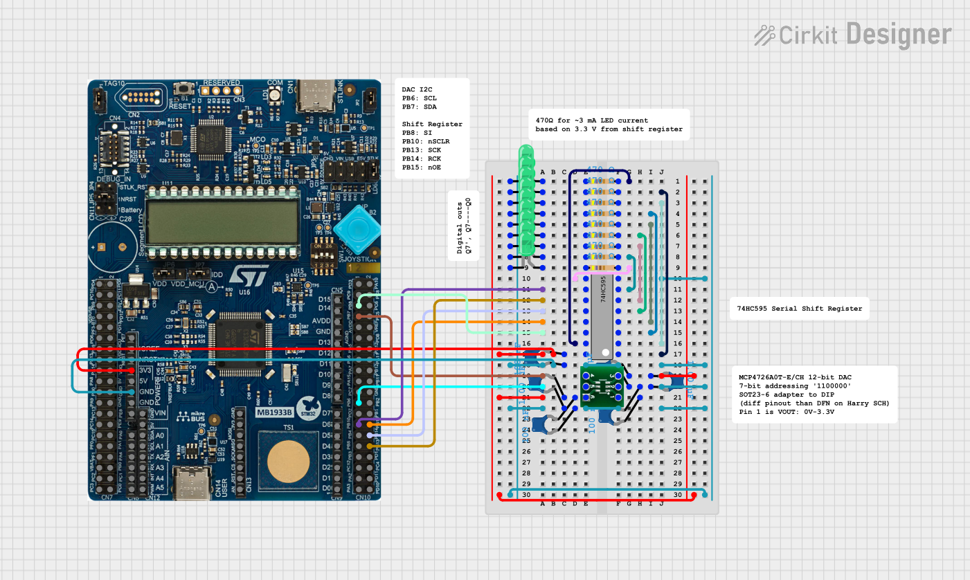
Circuit Documentation
Summary
This circuit appears to be designed to control a series of LEDs using a 74HC595 shift register, which is interfaced with an STM32U083C-DK microcontroller. The 74HC595 allows for the expansion of the microcontroller's I/O capabilities, enabling it to control multiple LEDs with fewer pins. The circuit also includes resistors to limit the current through the LEDs, capacitors for decoupling, and a 12-Bit DAC for analog voltage output, possibly for dimming control or another analog function.
Component List
Integrated Circuits
- 74HC595 Shift Register: An 8-bit serial-in, parallel-out shift register with output latches.
- STM32U083C-DK Microcontroller: A development kit with an STM32 microcontroller, used for controlling the shift register and other peripherals.
- 12-Bit DAC: A digital-to-analog converter that provides an analog voltage output.
Passive Components
- Resistors (470 Ohms): Current-limiting resistors for the LEDs.
- Ceramic Capacitors (100 nF and 1 µF): Used for power supply decoupling to reduce voltage spikes and noise.
LEDs
- LEDs (Green, Two Pin): Light-emitting diodes used as visual indicators.
Wiring Details
74HC595 Shift Register
- Q0-Q7: Connected to current-limiting resistors, which are then connected to the anodes of the LEDs.
- GND: Connected to the ground plane.
- VCC: Connected to a 3.3V power supply.
- DS (DATA): Connected to the microcontroller for serial data input.
- OE (Enable): Connected to the microcontroller, active low to enable output.
- ST_CP (RCLK): Connected to the microcontroller to latch the shift register data.
- SH_CP (SRCLK): Connected to the microcontroller to shift the data.
- MR (SRCLR): Connected to the microcontroller for clearing the shift register.
STM32U083C-DK Microcontroller
- GND: Connected to the ground plane.
- 3V3: Connected to the 3.3V power supply.
- PB10, PB13, PB14, PB15, PB8: Connected to the 74HC595 for control signals.
- PB7, PB6: Connected to the 12-Bit DAC for I2C communication.
12-Bit DAC
- VOUT: Connected to a ceramic capacitor and possibly to other circuitry for analog output.
- VSS: Connected to the ground plane.
- VREF: Connected to a 3.3V power supply.
- SCL: Connected to the microcontroller for I2C clock.
- SDA: Connected to the microcontroller for I2C data.
- VDD: Connected to a 3.3V power supply.
LEDs (Green, Two Pin)
- Anode: Connected to the output of the shift register through current-limiting resistors.
- Cathode: Connected to the ground plane.
Resistors (470 Ohms)
- Pin1: Connected to the anodes of the LEDs.
- Pin2: Connected to the outputs of the shift register.
Ceramic Capacitors (100 nF and 1 µF)
- Pin0 and Pin1: Connected across the power supply lines (VCC and GND) for decoupling.
Documented Code
No code was provided for the microcontroller or any other programmable components in the circuit. The code would typically initialize the microcontroller's peripherals, configure the I2C interface for communication with the DAC, and implement a routine to shift data into the 74HC595 to control the LEDs. Without the code, the specific functionality and behavior of the circuit cannot be fully documented.