Cirkit Designer
Your all-in-one circuit design IDE
Home /
Project Documentation
Arduino UNO 4x4 Keypad Input Logger

Circuit Documentation
Summary
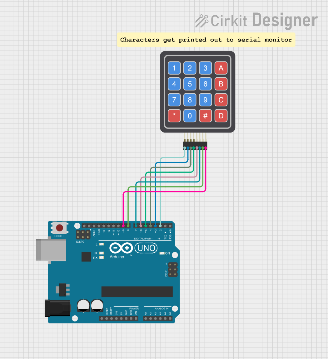
This circuit utilizes an Arduino UNO microcontroller and a 4x4 keypad to create an interactive input system. The keypad allows users to input numeric values and commands, which are then processed by the Arduino. The pressed keys are displayed on the Serial Monitor for feedback.
Component List
Arduino UNO
- Description: A microcontroller board based on the ATmega328P. It is used for building digital devices and interactive objects that can sense and control the physical world.
- Purpose: Acts as the main control unit for the circuit, processing inputs from the keypad and managing outputs.
4x4 Keypad
- Description: A matrix keypad with 4 rows and 4 columns, allowing for 16 different key inputs.
- Purpose: Provides a user interface for inputting data or commands to the Arduino.
Wiring Details
Arduino UNO
- D2: Connected to R1 of the 4x4 Keypad
- D3: Connected to R2 of the 4x4 Keypad
- D4: Connected to R3 of the 4x4 Keypad
- D5: Connected to R4 of the 4x4 Keypad
- D6: Connected to C1 of the 4x4 Keypad
- D7: Connected to C2 of the 4x4 Keypad
- D8: Connected to C3 of the 4x4 Keypad
- D9: Connected to C4 of the 4x4 Keypad
Documented Code
#include <Keypad.h>

// Define the number of rows and columns in the keypad
const byte ROWS = 4;
const byte COLS = 4;

// Define the keymap
char keys[ROWS][COLS] = {
  {'1','2','3','A'},
  {'4','5','6','B'},
  {'7','8','9','C'},
  {'*','0','#','D'}
};

// Connect keypad ROW0, ROW1, ROW2, ROW3 to these Arduino pins
byte rowPins[ROWS] = {2, 3, 4, 5};

// Connect keypad COL0, COL1, COL2, COL3 to these Arduino pins
byte colPins[COLS] = {6, 7, 8, 9};

// Create the Keypad
Keypad keypad = Keypad(makeKeymap(keys), rowPins, colPins, ROWS, COLS);

void setup() {
  Serial.begin(9600); // Initialize serial communication at 9600 baud
}

void loop() {
  char key = keypad.getKey(); // Get the key pressed

  if (key) { // If a key is pressed
    Serial.println(key); // Print the key to the Serial Monitor
  }
}
This documentation provides a comprehensive overview of the circuit, detailing the components used, their connections, and the code that drives the functionality of the system.