
ESP32-Controlled Obstacle Avoidance Robot with L298N Motor Driver and HC-SR04 Sensors
View and Edit Project In Cirkit Designer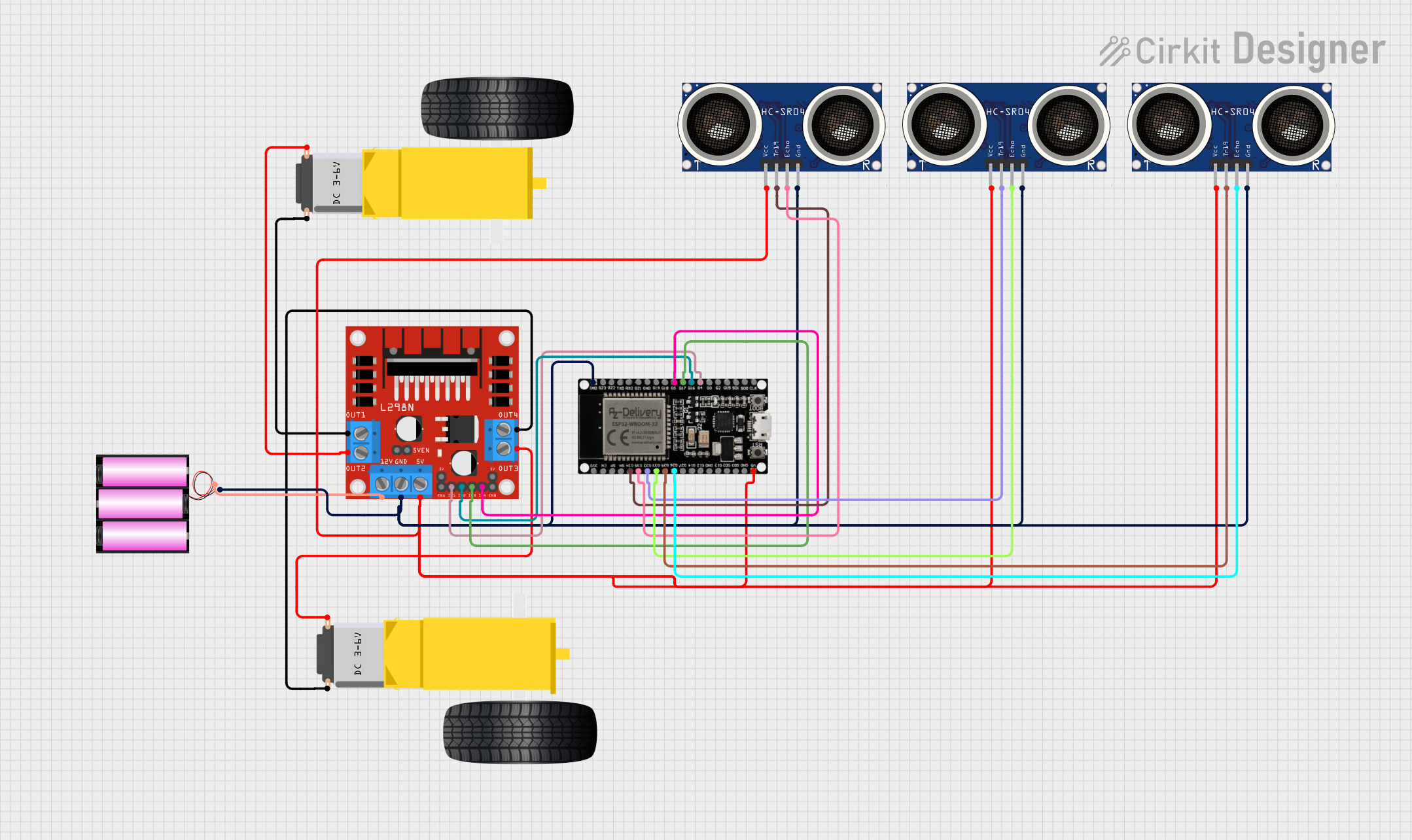
Circuit Documentation
Summary
This circuit is designed to control a robot with the capability to move in different directions while avoiding obstacles. It utilizes three HC-SR04 ultrasonic sensors to detect obstacles from the front, left, and right directions. The L298N DC motor driver is used to control the gearmotors attached to the robot's wheels, allowing it to move forward, backward, and turn. The ESP32 microcontroller is the brain of the robot, processing sensor data and sending control signals to the motor driver. A 12V battery provides the power source for the motor driver and the ESP32, which in turn powers the sensors.
Component List
L298N DC Motor Driver
- Description: A module used for controlling up to two DC motors with a maximum current of 2A per channel.
- Purpose: To drive the gearmotors for the robot's wheels.
Gearmotor DC Wheels (Left and Right)
- Description: DC motors with gear reduction that provide torque for the robot's movement.
- Purpose: To act as the driving force for the robot's wheels.
Sensor HC-SR04 (x3)
- Description: Ultrasonic distance sensors that can measure distances by emitting ultrasonic waves and measuring the time taken for the echo to return.
- Purpose: To detect obstacles in front of, to the left of, and to the right of the robot.
Battery 12V
- Description: A 12V power source.
- Purpose: To provide power to the motor driver and the ESP32 microcontroller.
ESP32 38 PINS
- Description: A microcontroller with Wi-Fi and Bluetooth capabilities and a wide range of GPIO pins.
- Purpose: To process sensor data and control the motor driver based on the sensor inputs.
Wiring Details
L298N DC Motor Driver
5Vconnected to ESP325V(Power supply for logic)GNDconnected to Battery-(Ground connection)12Vconnected to Battery+(Motor power supply)OUT1andOUT2connected to Right Gearmotor pinsOUT3andOUT4connected to Left Gearmotor pinsIN1,IN2,IN3,IN4connected to ESP32 GPIOsG4,G16,G17,G5respectively (Control signals from ESP32)
Gearmotor DC Wheels (Left and Right)
- Left Gearmotor connected to
OUT3andOUT4of L298N - Right Gearmotor connected to
OUT1andOUT2of L298N
Sensor HC-SR04 (Front, Left, Right)
- All
VCCpins connected to ESP325V(Power supply) - All
GNDpins connected to Battery-(Ground connection) - Front Sensor
TRIGconnected to ESP32G34 - Front Sensor
ECHOconnected to ESP32G35 - Left Sensor
TRIGconnected to ESP32G32 - Left Sensor
ECHOconnected to ESP3233 - Right Sensor
TRIGconnected to ESP32G25 - Right Sensor
ECHOconnected to ESP32G26
Battery 12V
+connected to L298N12V(Motor power supply)-connected to L298NGNDand all HC-SR04GNDpins (Common ground)
ESP32 38 PINS
5Vconnected to all HC-SR04VCCpins (Power supply for sensors)GNDconnected to Battery-(Common ground)- GPIOs
G34,G35,G32,33,G25,G26connected to corresponding HC-SR04TRIGandECHOpins - GPIOs
G4,G16,G17,G5connected to L298NIN1,IN2,IN3,IN4(Motor control signals)
Documented Code
/*
 * This code controls a robot that moves forward, backward, left, and right
 * to avoid obstacles using three HC-SR04 sensors positioned at the front,
 * left, and right. The L298N motor driver controls the motors, and the ESP32
 * microcontroller processes the sensor data and controls the motor driver.
 */

#define TRIG_FRONT 34
#define ECHO_FRONT 35
#define TRIG_LEFT 32
#define ECHO_LEFT 33
#define TRIG_RIGHT 25
#define ECHO_RIGHT 26
#define IN1 4
#define IN2 16
#define IN3 17
#define IN4 5

void setup() {
  pinMode(TRIG_FRONT, OUTPUT);
  pinMode(ECHO_FRONT, INPUT);
  pinMode(TRIG_LEFT, OUTPUT);
  pinMode(ECHO_LEFT, INPUT);
  pinMode(TRIG_RIGHT, OUTPUT);
  pinMode(ECHO_RIGHT, INPUT);
  pinMode(IN1, OUTPUT);
  pinMode(IN2, OUTPUT);
  pinMode(IN3, OUTPUT);
  pinMode(IN4, OUTPUT);
}

long readDistance(int trigPin, int echoPin) {
  digitalWrite(trigPin, LOW);
  delayMicroseconds(2);
  digitalWrite(trigPin, HIGH);
  delayMicroseconds(10);
  digitalWrite(trigPin, LOW);
  return pulseIn(echoPin, HIGH) * 0.034 / 2;
}

void moveForward() {
  digitalWrite(IN1, HIGH);
  digitalWrite(IN2, LOW);
  digitalWrite(IN3, HIGH);
  digitalWrite(IN4, LOW);
}

void moveBackward() {
  digitalWrite(IN1, LOW);
  digitalWrite(IN2, HIGH);
  digitalWrite(IN3, LOW);
  digitalWrite(IN4, HIGH);
}

void turnLeft() {
  digitalWrite(IN1, LOW);
  digitalWrite(IN2, HIGH);
  digitalWrite(IN3, HIGH);
  digitalWrite(IN4, LOW);
}

void turnRight() {
  digitalWrite(IN1, HIGH);
  digitalWrite(IN2, LOW);
  digitalWrite(IN3, LOW);
  digitalWrite(IN4, HIGH);
}

void stopMoving() {
  digitalWrite(IN1, LOW);
  digitalWrite(IN2, LOW);
  digitalWrite(IN3, LOW);
  digitalWrite(IN4, LOW);
}

void loop() {
  long distanceFront = readDistance(TRIG_FRONT, ECHO_FRONT);
  long distanceLeft = readDistance(TRIG_LEFT, ECHO_LEFT);
  long distanceRight = readDistance(TRIG_RIGHT, ECHO_RIGHT);

  if (distanceFront < 20) {
    stopMoving();
    delay(500);
    if (distanceLeft < distanceRight) {
      turnRight();
    } else {
      turnLeft();
    }
    delay(500);
  } else {
    moveForward();
  }
  delay(100);
}
This code is responsible for initializing the GPIO pins connected to the HC-SR04 sensors and the L298N motor driver. It defines functions to read distances from the sensors and to control the motors for moving forward, backward, turning left, and turning right. The loop function continuously checks the distances from the sensors and decides the movement of the robot accordingly. If an obstacle is detected within 20 cm from the front sensor, the robot stops, determines the direction with more space (left or right), and turns accordingly. If no obstacle is detected, the robot moves forward.